
Metering assembly and customer load panel for power delivery

a technology of power delivery and load panel, applied in the field of power delivery, can solve the problems of limited power generation capability of generators and difficulty in managing the delivery of power from backup sources

Inactive Publication Date: 2009-06-11
OP ENERGY SYST INC
View PDF20 Cites 52 Cited by
  • Summary
  • Abstract
  • Description
  • Claims
  • Application Information

AI Technical Summary

Benefits of technology

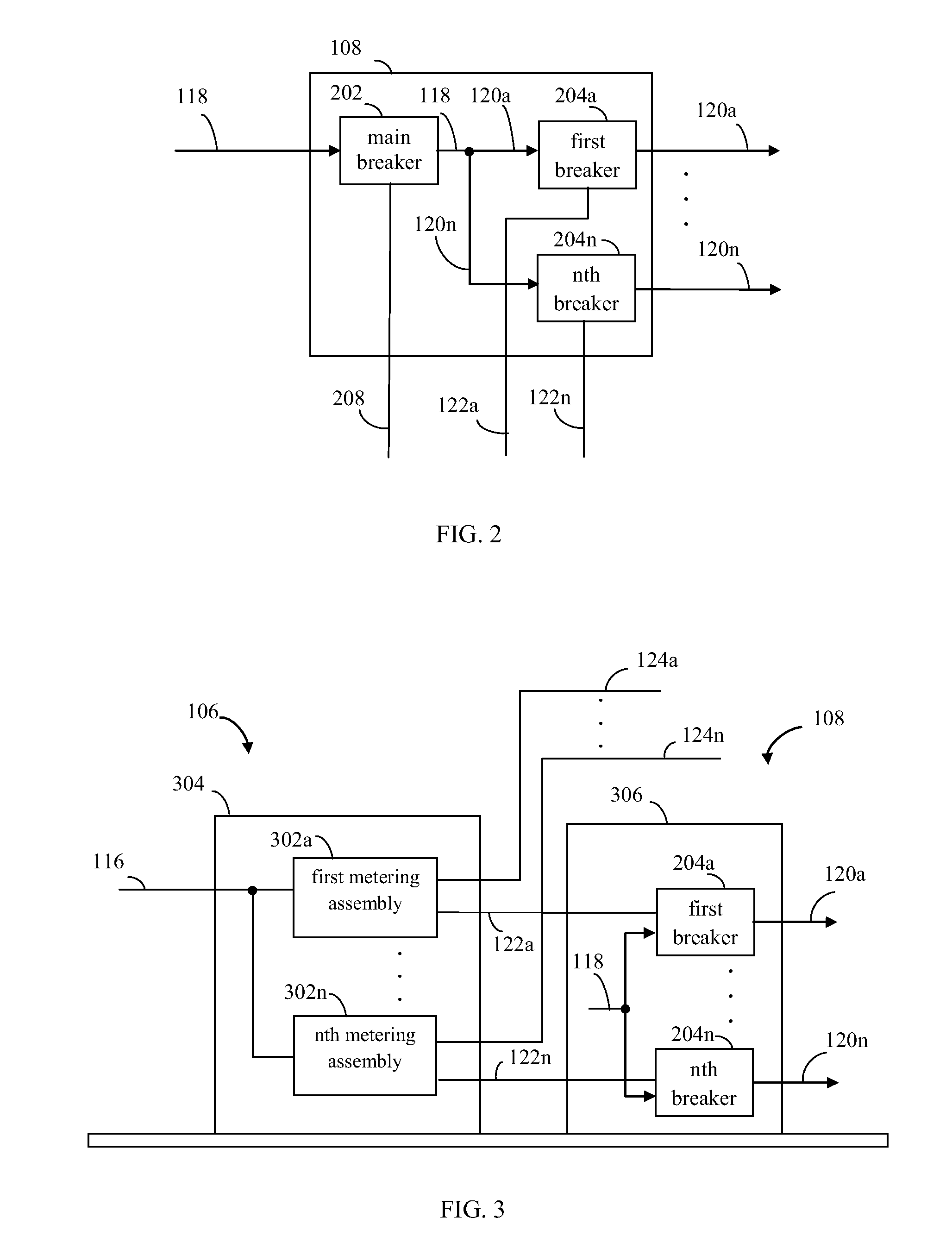
[0009]In an example implementation, the metering assembly includes a power meter module. The power meter module includes a power control module and a power monitor. The power control module is coupled to the transfer switch. The power control module is configured to receive a request from the transfer switch for the alternate power to be supplied through the transfer switch to the electrical circuit load. The power control module is configured to enable the transfer switch to supply the alternate power to the electrical circuit load in response to the request.
[0010]In a further aspect, the power monitor is configured to determine an amount of the alternate power provided to the electrical circuit load through the transfer switch. The power control module is configured to enable the alternate power to be decoupled from the electrical circuit load if the determined amount of the alternate power provided to the electrical circuit load is greater than a power trip setpoint.

Problems solved by technology

Office building tenants are increasingly sensitive to the quality and reliability of their electric power.
However, onsite power generators have limited power generation capability as compared to electric utilities, and can fail when suddenly having to supply a heavy current load, such as when being powered up after the loss of the primary power source.
Such limitations increase a difficulty in managing the delivery of power from backup sources during loss of primary power.

Method used


Image

  • Metering assembly and customer load panel for power delivery
  • Metering assembly and customer load panel for power delivery
  • Metering assembly and customer load panel for power delivery

Examples


example embodiments

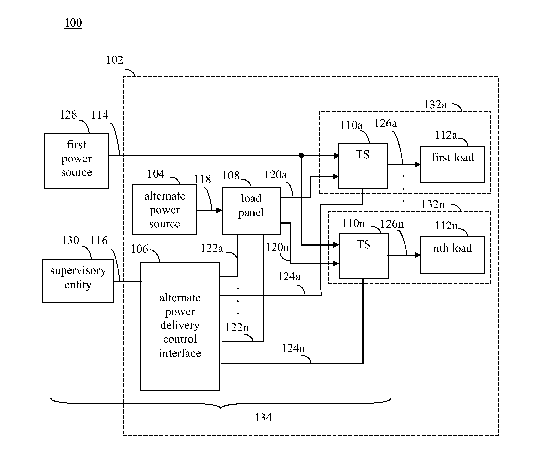
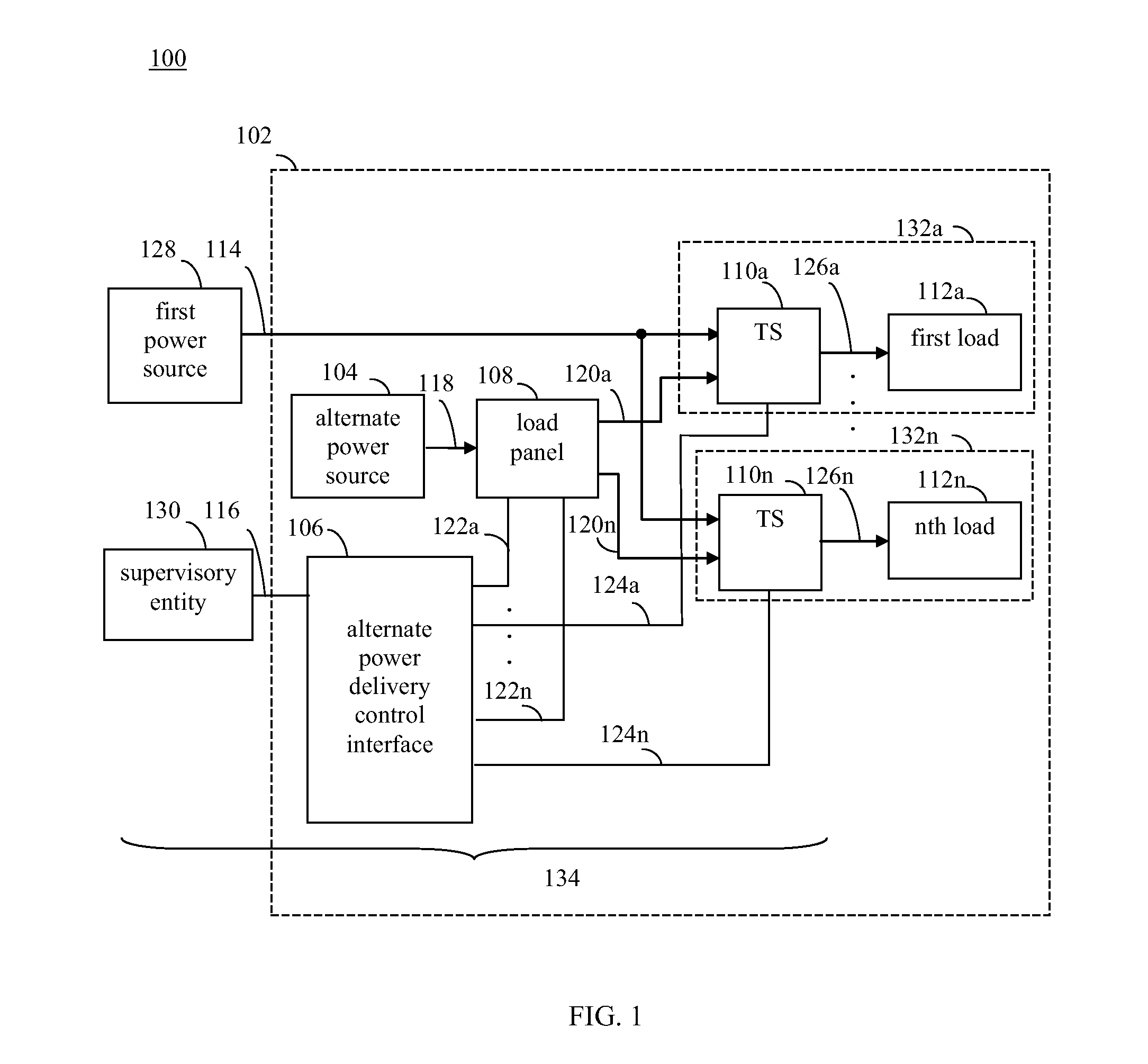
[0039]Methods, systems, and apparatuses are provided for power delivery in environments where a main power source and an alternate power source are available. For example, the alternate power source may be a backup power source to the main power source. Embodiments enable power to be supplied by the alternate power source to electrical circuit loads when desired, such as during a failure of the main power source. Furthermore, embodiments enable monitoring of supplied alternate power, sequencing of loads to receive alternate power, shedding of loads from alternate power, and / or other functions.

[0040]The example embodiments described herein are provided for illustrative purposes, and are not limiting. Further structural and operational embodiments, including modifications and / or alterations, will become apparent to persons skilled in the relevant art(s) from the teachings herein.

[0041]FIG. 1 shows a block diagram of a power delivery environment 100, according to an example embodiment ...


PUM


Abstract

Methods, systems, and apparatuses for alternate power delivery are provided. A metering assembly includes a power meter module. The power meter module includes a power control module and a power monitor. The power control module is coupled to a transfer switch that receives both primary power and alternate power. The transfer switch has an output coupled to an electrical circuit load. The power control module is configured to receive a request from the transfer switch for the alternate power to be supplied through the transfer switch to the electrical circuit load. The power control module is configured to enable the transfer switch to supply the alternate power to the electrical circuit load in response to the request. The power monitor is configured to determine an amount of the alternate power provided to the electrical circuit load. The power control module is configured to enable the alternate power to be decoupled from the electrical circuit load if the determined amount of the alternate power provided to the electrical circuit load is greater than a power trip setpoint. A plurality of metering assemblies may be provided to monitor a corresponding number of transfer switches coupled to electrical circuit loads in a facility.

Description

BACKGROUND OF THE INVENTION[0001]1. Field of the Invention[0002]The present invention relates generally to power delivery, and more particularly, to the control and monitoring of backup power delivered to one or more loads.[0003]2. Background Art[0004]Office building tenants are increasingly sensitive to the quality and reliability of their electric power. Many are expanding their investment in and reliance upon sophisticated computer and telecommunications equipment and networks that are increasingly vulnerable to grid-related power fluctuations and outages. To retain existing tenants and to attract new ones, office building owners need to establish a new standard of service that delivers power with reliability and quality that effectively addresses these growing concerns.[0005]One approach for providing such a standard of service involves installing onsite power generation equipment for backup power. When power is lost from the electric utility that normally provides power, the on...

Claims


Application Information

Patent Timeline
Patent Type & Authority Applications(United States)
IPC IPC(8): H02J3/06H02J3/14G01R21/06G05B15/00
CPCH02J9/06
Inventor PIFER, JOHN S.EDWARDS, ANDREW J.
Owner OP ENERGY SYST INC
Learn More