
Retrofit kit for converting a transfer switch to a switch for soft-load transfer, and soft-load power distribution system and method

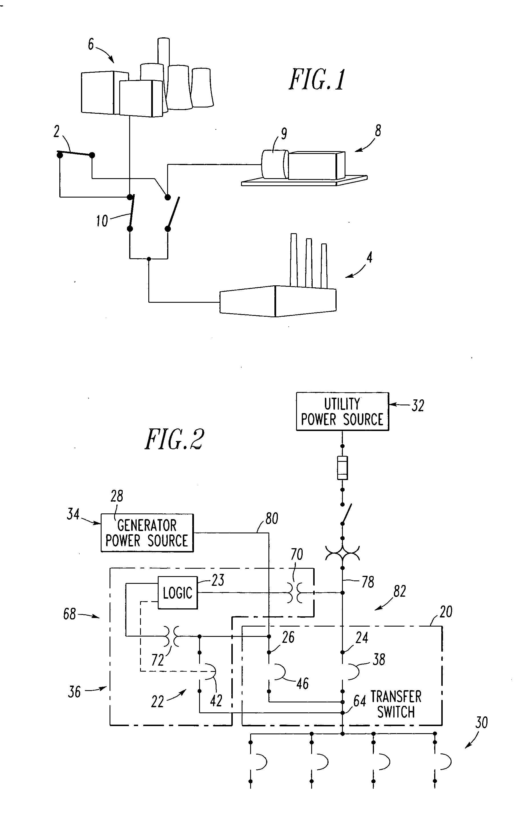
a transfer switch and retrofit kit technology, applied in emergency protective devices, emergency protective devices, emergency protective circuit arrangements, etc., can solve the problems of not being able to withstand a long interruption of electric power, not being able to facilitate a transfer, and not including any mechanism for smooth disconnecting

Inactive Publication Date: 2006-02-09
EATON CORP
View PDF17 Cites 53 Cited by
  • Summary
  • Abstract
  • Description
  • Claims
  • Application Information

AI Technical Summary

Benefits of technology

[0014] These needs and others are met by the present invention, which allows a conv

Problems solved by technology

Alternate power sources are provided for any number of applications, which cannot withstand a lengthy interruption in electric power.
However, known peaking switches are designed to supply the load from both sources and do not include a method of disconnecting the load from one source and transferring the load to the second source as would be needed, for example, during monthly generator testing at, for example, a hospital, when the goal is, for example, to transfer the load from the utility power source to the generator power source for such testing and, then, to disconnect from the utility power source without causing a transient during such transfer.
Known peaking switches also do not facilitate a transfer, since while they permit paralleling of two sources, they do not include any mechanism to smoothly disconnect one source while maintaining a live source continuously connected to the load.
Those circumstances include, for example: (1) wiring was previously cut and terminated at existing terminals that may or may not reach new equipment termination points, necessitating new cabling be pulled; or (2) the inability to remove or install a new transfer switch due to subsequent construction of the facility that has now limited entry or egress of oversized equipment.

Method used


Image

  • Retrofit kit for converting a transfer switch to a switch for soft-load transfer, and soft-load power distribution system and method
  • Retrofit kit for converting a transfer switch to a switch for soft-load transfer, and soft-load power distribution system and method
  • Retrofit kit for converting a transfer switch to a switch for soft-load transfer, and soft-load power distribution system and method

Examples


example 1

[0046] As shown in FIGS. 4A and 5A1-5A2, if the controller 84 of the transfer switch20 supports the external “go to emergency” input 66, then the STR device 36 (FIG. 2) drives that input from the output 76.

example 2

[0047] If the option of Example 1 is not available, then the STR device 36 places dry contacts 86,88, as shown in FIGS. 4B and 5B1-5B2, into one phase's (e.g., phase A) voltage sense lead 90,92 on both the utility and generator power sources 32,34, respectively. Since both power sources 32,34 are available, a “failure” caused by one of the contacts 86,88 being open on one of those sources 32,34, respectively, will cause an immediate transfer to the other source by the transfer switch controller 84.

[0048] In this example, the third input of the transfer switch 20 (FIG. 2) includes the utility (phase A) voltage sense input 90 (FIGS. 4B and 5B1-5B2) receiving the utility AC voltage (Va) of the voltages 102 and the generator (phase A) voltage sense input 92 receiving the generator AC voltage (Va) of the voltages 104. The controller 74 includes the first contact 86 adapted to be electrically connected in series with the utility voltage sense input 90, and the second contact 88 adapted t...


PUM


Abstract

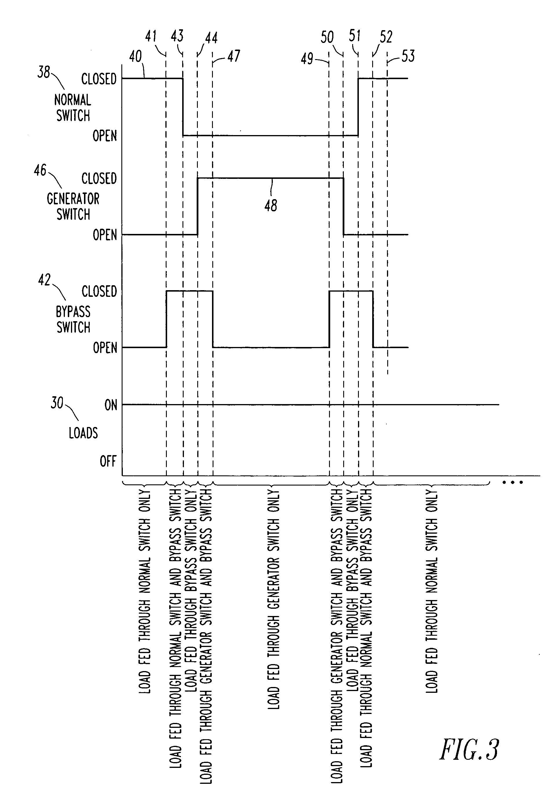
A soft-load power distribution system includes a transfer switch having a first input to a utility power source with a utility alternating current (AC) voltage, a second input to a generator power source with a generator AC voltage, and an output to a load. A first switch is electrically connected between the first input and the output and a second switch is electrically connected between the second input and the output. The transfer switch has a third input, such as a go to emergency input, controlling the first and second switches. A bypass switch is electrically connected between the second input and the output. First and second sensors, such as potential transformers, sense the utility and generator AC voltages, respectively. A controller closes the bypass switch when the utility AC voltage is within a predetermined range of the generator AC voltage, and includes an output controlling the third input.

Description

BACKGROUND OF THE INVENTION [0001] 1. Field of the Invention [0002] The present invention relates to power distribution systems and, more particularly, to such systems employing transfer mechanisms, such as, for example, transfer switches. The invention also relates to a retrofit kit for a transfer mechanism, such as, for example, as transfer switch. [0003] 2. Background Information [0004] Alternate power sources are provided for any number of applications, which cannot withstand a lengthy interruption in electric power. Typically, power is provided from a primary source with back-up power provided by a secondary source. Often, the primary source is a utility power source and the secondary source is an auxiliary power source, such as an engine driven generator or a second utility source. The transfers between the two power sources can be made automatically or manually. [0005] Transfer switches are well known in the art. See, for example, U.S. Pat. Nos. 5,397,868; 5,210,685; 4,894,79...

Claims


Application Information

Patent Timeline
IPC IPC(8): H02H3/24
CPCH02J3/005H02J3/007
Inventor LOUCKS, DAVID G.HANNA, JAMES R.PATURA, KRZYSZTOFLATHROP, TODD M.HARTZEL, RONALD D.
Owner EATON CORP
Learn More