
Method, program product and apparatus for model based geometry decomposition for use in a multiple exposure process

a technology of model based geometry and program product, which is applied in special data processing applications, optics, instruments, etc., can solve the problems of not being able to image individual features, being increasingly difficult to reproduce target patterns on wafers, and being difficult to achieve single feature image,

Active Publication Date: 2009-06-11
ASML NETHERLANDS BV
View PDF39 Cites 24 Cited by
  • Summary
  • Abstract
  • Description
  • Claims
  • Application Information

AI Technical Summary

Benefits of technology

This approach enables the decomposition of target patterns into distinct segments for improved imaging performance, achieving a k value of 0.195, overcoming limitations of existing methods by automatically decomposing single features into multiple segments and reducing the need for complex rules.

Problems solved by technology

These rules are set by processing and design limitations.
As the critical dimensions of the target patterns become increasingly smaller, it is becoming increasingly harder to reproduce the target patterns on the wafer.
Such a technique is typically utilized when the target features are spaced so closely together that it is not possible to image the individual features.
However, problems and limitations still exist with currently known double exposure techniques.
As a result, for certain target patterns, even though double exposure techniques are utilized, it is not possible to obtain a k1<0.25.
Another problem associated with current decomposition algorithms is that they are primarily rule based algorithms, which require an excessive number of rules to handle today's increasingly complex designs.
Moreover, often times there are situations / conflicts within the design for which no rule has been defined, and such instances can result in the algorithm failing to find a suitable result.

Method used


Image

  • Method, program product and apparatus for model based geometry decomposition for use in a multiple exposure process
  • Method, program product and apparatus for model based geometry decomposition for use in a multiple exposure process
  • Method, program product and apparatus for model based geometry decomposition for use in a multiple exposure process

Examples


Embodiment Construction

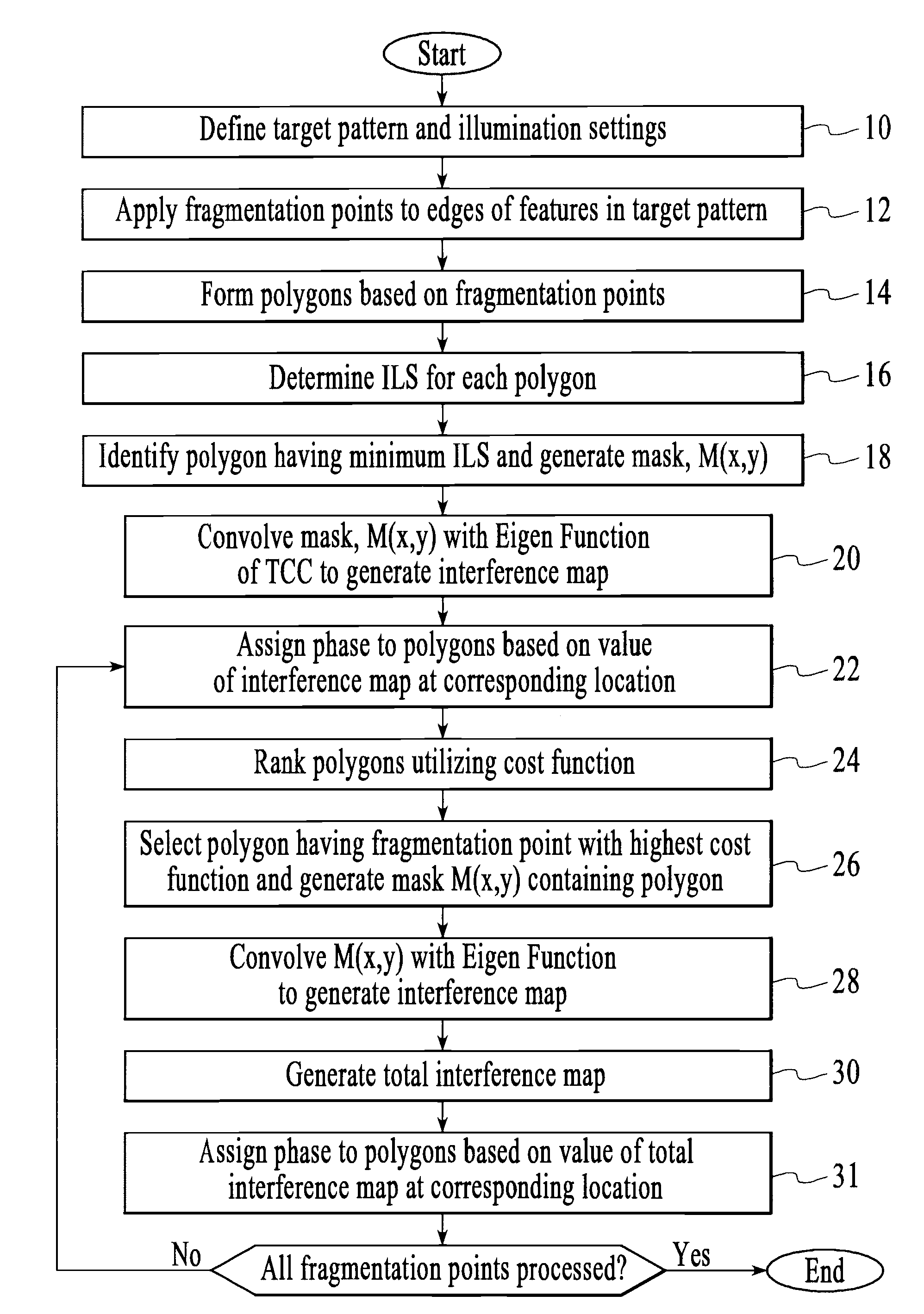
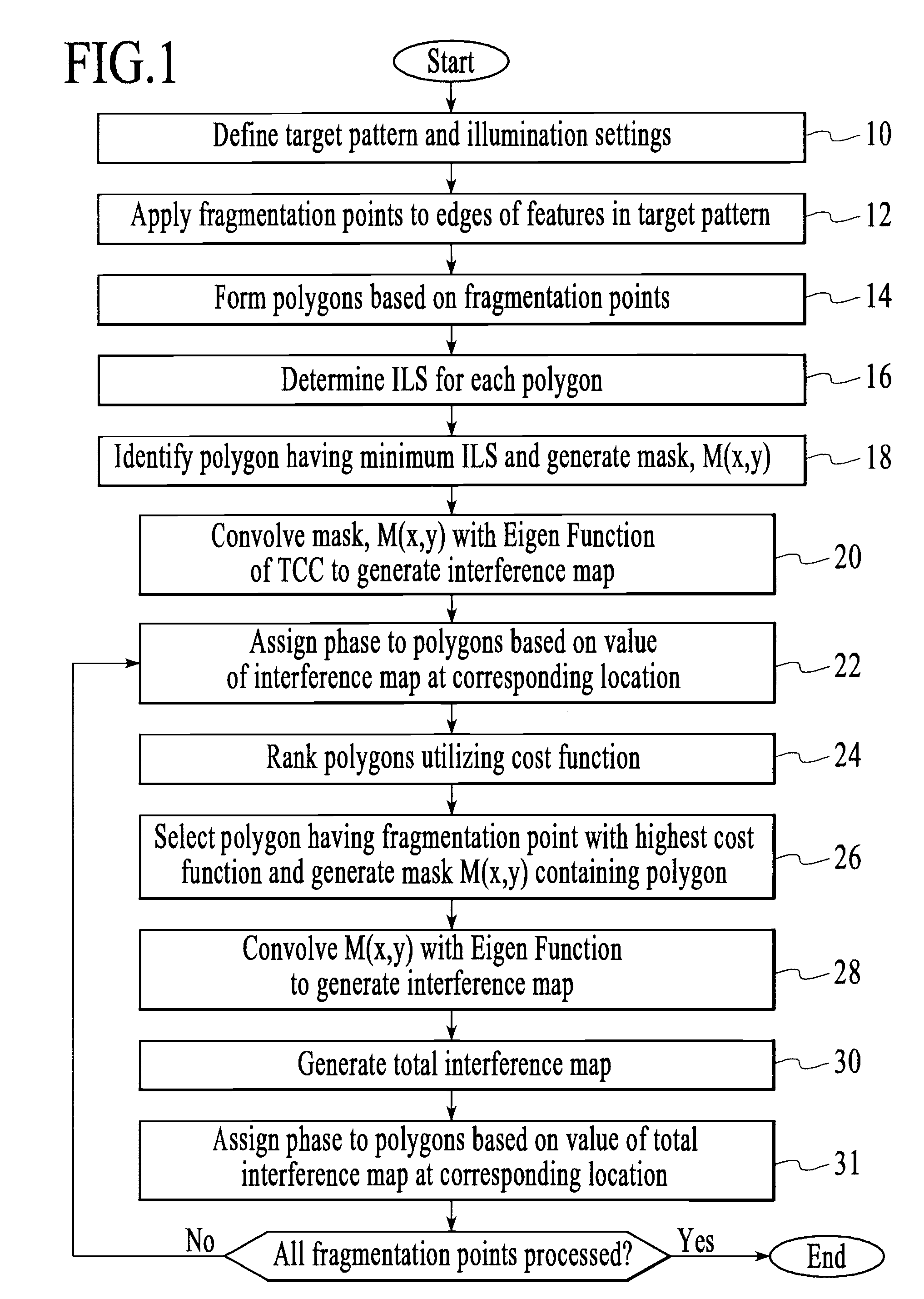
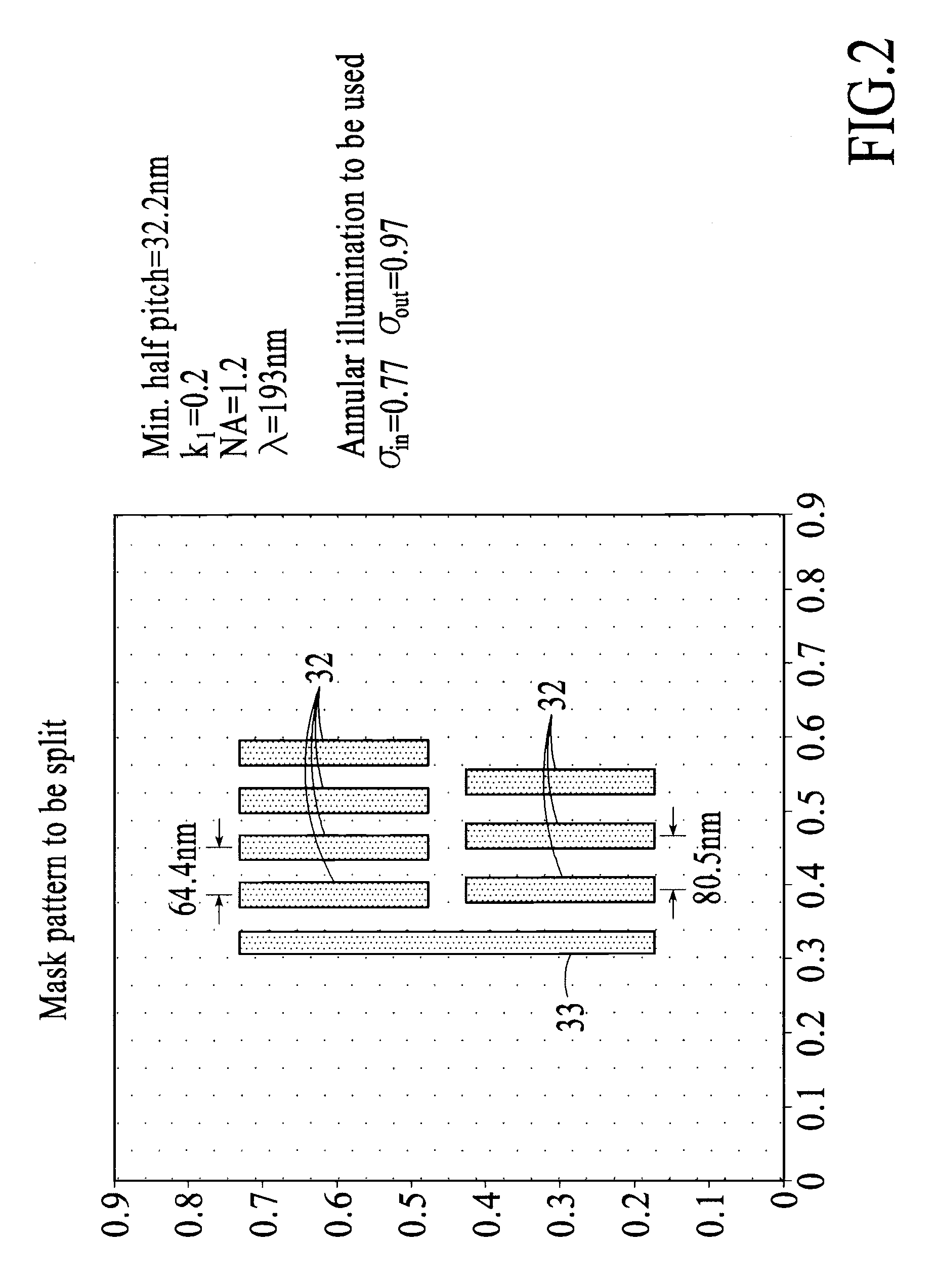
[0038]As explained in more detail below, the model based coloring process decomposes a target pattern into multiple segments which are illuminated separately in a multiple exposure process. In one embodiment, the multiple segments are assigned and included in one of two separate reticles, which are subsequently illuminated. Furthermore, as shown in the examples disclosed herein, the model based coloring process, when necessary, automatically provides for decomposition of single geometry (i.e., feature) in the target pattern into multiple segments, which are then imaged in separate illumination processes.

[0039]Referring to FIG. 1, which is an exemplary flowchart of the model based coloring process, the first step in the process (Step 10) is to define the target pattern (i.e., the pattern to be imaged on the substrate) and the illumination settings that will be utilized to image the target pattern. The target pattern is preferably described in a data format, such as “gds”, which is a ...


PUM

PropertyMeasurementUnit
wavelengthaaaaaaaaaa

Abstract

A method of decomposing a target pattern having features to be imaged on a substrate so as to allow said features to be imaged in a multi-exposure process. The method includes the steps of: (a) segmenting a plurality of the features into a plurality of polygons; (b) determining the image log slope (ILS) value for each of the plurality of polygons; (c) determining the polygon having the minimum ILS value, and defining a mask containing the polygon; (d) convolving the mask defined in step (c) with an eigen function of a transmission cross coefficient so as to generate an interference map, where the transmission cross coefficient defines the illumination system to be utilized to image the target pattern; and (e) assigning a phase to the polygon based on the value of the interference map at a location corresponding to the polygon, where the phase defines which exposure in said multiexposure process the polygon is assigned.

Description

RELATED APPLICATIONS[0001]This application claims priority to U.S. patent application Ser. No. 11 / 496,742, filed on Aug. 1, 2006, and to U.S. Patent Application Ser. No. 60 / 754,312, filed on Dec. 29, 2005, and to U.S. Patent Application Ser. No. 60 / 776,199 filed on Feb. 24, 2006, all of which are incorporated by reference herein in their entirety.TECHNICAL FIELD[0002]The technical field of the present invention relates generally to a method, program product and apparatus for performing a model based decomposition of a target pattern so as to allow the target pattern to be imaged utilizing, for example, multiple masks in a multiple illumination process.BACKGROUND OF THE INVENTION[0003]Lithographic apparatus can be used, for example, in the manufacture of integrated circuits (ICs). In such a case, the mask may contain a circuit pattern corresponding to an individual layer of the IC, and this pattern can be imaged onto a target portion (e.g., comprising one or more dies) on a substrate...

Claims


Application Information

Patent Timeline
Patent Type & Authority Applications(United States)
IPC IPC(8): G03F1/00G06F17/50
CPCG03F1/144G03F1/36G03F7/705G03F7/70466G03F7/70433G03F1/70G03F7/701G03F7/70633G03F7/70653H01L21/0275H01L21/3085H01L21/3213
Inventor SOCHA, ROBERT JOHN
Owner ASML NETHERLANDS BV
Learn More