
Adhesion assisting agent-bearing metal foil, printed wiring board, and production method of printed wiring board

a technology of adhesive agent and wire, which is applied in the direction of insulating substrate metal adhesion improvement, conductive pattern formation, and dielectric characteristics, etc., can solve the problems of undesirable deterioration of electric properties, difficult to form a built-up layer on a core substrate or a solder resist on a substrate, and achieve excellent high frequency properties. , the effect of improving the adhesion strength of the resin and the bonding strength

Active Publication Date: 2009-06-11
RESONAC CORPORATION
View PDF17 Cites 6 Cited by
  • Summary
  • Abstract
  • Description
  • Claims
  • Application Information

AI Technical Summary

Benefits of technology

[0012]According to one embodiment of the invention, it is made possible to provide a wiring board advantageous in the ultra fine wiring formation, electric properties, and production cost and having high reliability and excellent high frequency properties.
[0013]Also, according to another embodiment of the invention, it is made possible to provide a printed wiring board having improved resin-resin adhesion strength and excellent moisture absorption resistance and heat resistance.
[0014]Further, according to another embodiment of the invention, it is made possible to provide a printed wiring board having improved resin-metal adhesion strength and excellent moisture absorption resistance and heat resistance.

Problems solved by technology

However, according to these methods, the roughened shape adversely interferes with the fine wiring formation and also the electric properties are undesirably deteriorated due to the roughened shape.
However, if the resin is made smooth in those methods, it becomes difficult to form a resin layer thereon.
In other words, it becomes difficult to form a built-up layer on a core substrate or to form a solder resist on a substrate.
Even if laminating seems to be done, the substrate is very poor in resistance to moisture absorption and heat resistance in many cases.

Method used


Image

  • Adhesion assisting agent-bearing metal foil, printed wiring board, and production method of printed wiring board
  • Adhesion assisting agent-bearing metal foil, printed wiring board, and production method of printed wiring board
  • Adhesion assisting agent-bearing metal foil, printed wiring board, and production method of printed wiring board

Examples


example 1

[0152]The following metal foil A was produced.

[0153](Metal Foil A)

[0154]Chromium plating was continuously carried out on the bright face of an electrolytic copper foil (a carrier copper foil) with a width of 510 mm and a thickness of 35 μm in the following conditions to form a chromium plating layer (a separation layer) with a thickness of 1.0 mg / dm2. The surface roughness (ten-point mean surface roughness) Rz after the chromium plating formation was 0.5 μm. The surface roughness was measured according to JIS-B-0601.

Chromium Plating Conditions

[0155]Solution composition: chromium trioxide 250 g / L and sulfuric acid 2.5 g / L,

[0156]Bath temperature: 25° C.,

[0157]Anode: lead, and

[0158]Electric current density: 20 A / dm2.

[0159]Next, electric copper plating in a thickness of 2.0 μm was carried out in the following bright conditions. The metal foil surface roughness Rz after the electric copper plating was 0.6 μm.

Electric Copper Plating Conditions

[0160]Solution composition: copper sulfate pen...

example 2

[0204]A printed wiring board was produced in the same manner as Example 1, except that at the time of producing the resin composition A, the addition amount of the novolak type epoxy resin having biphenyl structure (NC3000S-H) was changed to 82.8 parts by weight from 80 parts by weight and the addition amount of the cresol novolak type phenol (Phenolite EXB-9829) was changed to 12.2 parts by weight from 9 parts by weight.

example 3

[0205]A printed wiring board was produced in the same manner as Example 1, except that the thickness of the resin composition A was changed to 5 μm from 2.0 μm at the time of producing the metal foil B.


PUM

PropertyMeasurementUnit
thicknessaaaaaaaaaa
thicknessaaaaaaaaaa
thicknessaaaaaaaaaa

Abstract

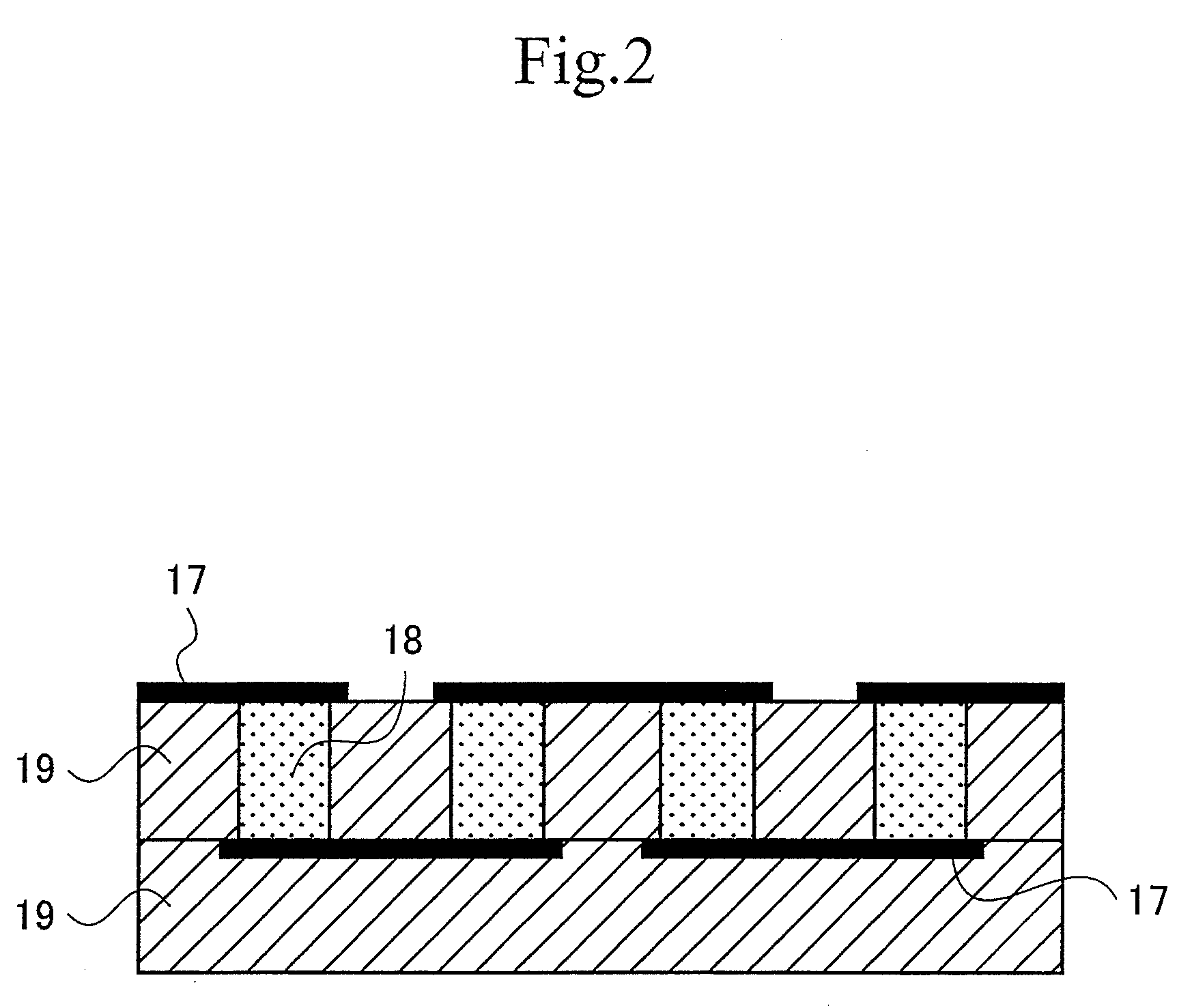
The invention relates to an adhesion assisting agent-bearing metal foil comprising a layer of an adhesion assisting agent containing an epoxy resin as an indispensable component on a metal, wherein the adhesion assisting agent layer has a thickness of 0.1 to 10 μm. The invention also relates to a printed wiring board being a multilayer wiring board having a plurality of layers, wherein an adhesion assisting agent layer is formed between insulating layers.

Description

[0001]The application is a Divisional application of application Ser. No. 11 / 044,533, filed Jan. 28, 2005, the contents of which are incorporated herein by reference in their entirety.BACKGROUND OF THE INVENTION[0002]1. Field of the Invention[0003]The invention relates to an adhesion assisting agent-bearing metal foil, a printed wiring board, and a production method of the printed wiring board. The invention also relates to a multilayer circuit board, a semiconductor chip-mounting substrate, and a semiconductor package substrate.[0004]2. Description of the Related Art[0005]Recently, electronic appliances have been required to be compact, lightweight and high speed, and high densification of printed wiring boards has advanced and in these years, therefore, production of a printed wiring board by a semi-additive method using electroplating has been drawing attention.[0006]As a semi-additive method, Japanese Patent Application Laid-Open (JP-A) No. 10-4254 (application date: Jun. 14, 19...

Claims


Application Information

Patent Timeline
Patent Type & Authority Applications(United States)
IPC IPC(8): C25D5/02C25D5/48B32B3/00H05K1/00H05K3/00H05K3/10H05K3/28H05K3/38H05K3/46
CPCH05K3/108Y10T428/24917H05K3/386H05K3/389H05K3/4652H05K3/4655H05K2201/0133H05K2201/0154H05K2201/0195H05K2201/0212H05K2201/0358H05K2203/0759Y10T428/2804Y10T428/12431Y10T428/287H05K3/28Y10T428/31681B66C3/02B66C13/00
Inventor TAKAI, KENJIMORIIKE, NORIOKAMIYAMA, KENICHIWATANABE, TAKAKOTAKANEZAWA, SHINMORITA, KOJIMASUDA, KATSUYUKIHASEGAWA, KIYOSHI
Owner RESONAC CORPORATION
Learn More