Image display system

a display system and image technology, applied in the field of image display systems, can solve the problems of increasing the cost as a whole, shortening the frame period, and not addressing the solution of the blurring phenomenon of moving images, and achieve the effect of reducing the memory cos

Inactive Publication Date: 2009-06-04
MITSUBISHI ELECTRIC CORP
View PDF8 Cites 24 Cited by
  • Summary
  • Abstract
  • Description
  • Claims
  • Application Information

AI Technical Summary

Benefits of technology

[0016]An object of the present invention is to provide an image display system that includes an image display device having an overdrive processing circuit and allows reduction in memory cost as a whole.
[0018]In the image display system according to this aspect of the present invention, the image generation device includes the rendering circuit, the memory unit that holds plural pieces of image data corresponding to at least two frames, and the transfer circuit that transfers the plural pieces of image data corresponding to two frames to the image display device within one frame period, and the image display device receives the plural pieces of image data corresponding to the two frames from the transfer circuit and performs the overdrive processing based on the received image data. Therefore, this image display system allows reduction in memory cost as a whole while maintaining display quality.

Problems solved by technology

However, these methods are not pertain to solution of the problem of the moving image blurring phenomenon.
In other words, when the liquid crystal display device is driven at a high speed, the frame period becomes short.
The image display system described above requires two memories, that is, the graphic memory in the image generation device and a frame memory in the image display device, leading to increase in cost as a whole.

Method used


Image

  • Image display system
  • Image display system
  • Image display system

Examples


first embodiment

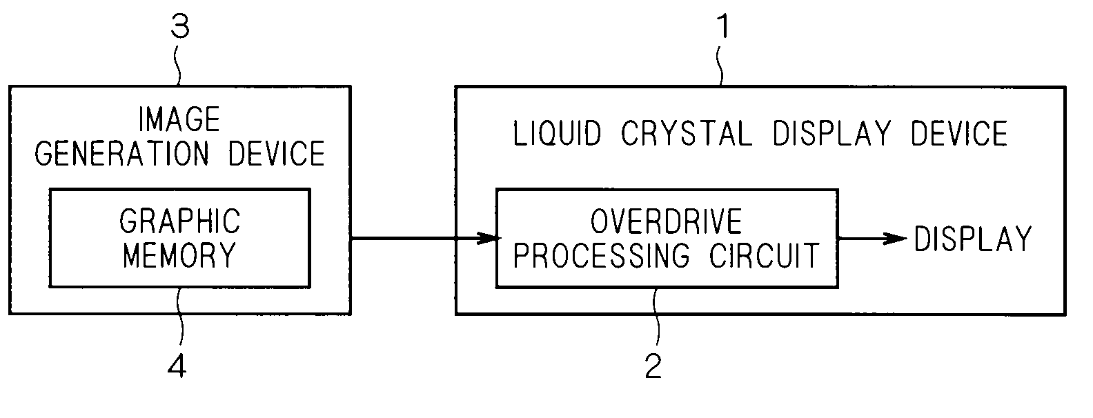
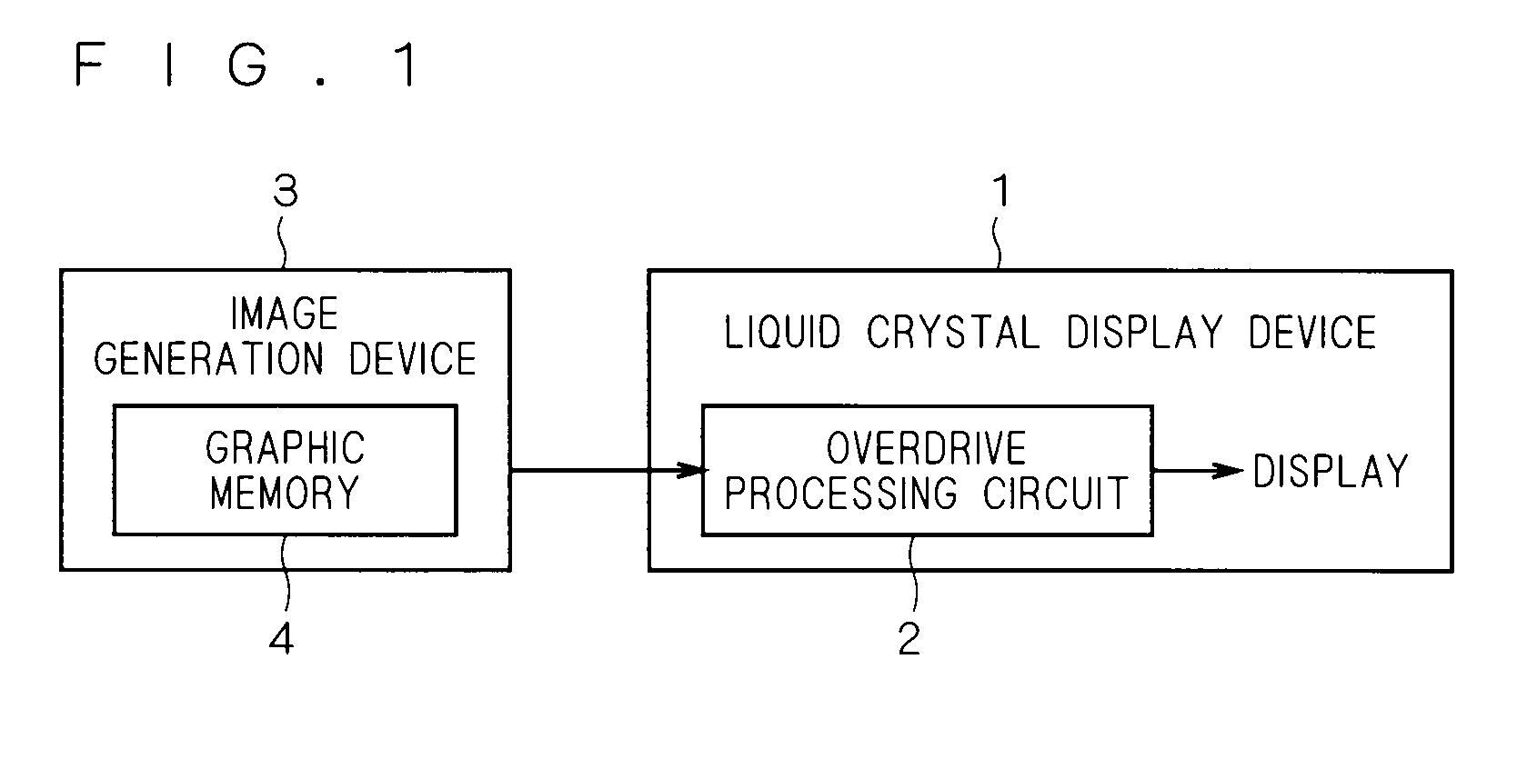
[0040]FIG. 1 shows a block diagram of an image display system according to a first embodiment of the present invention. As shown in FIG. 1, a liquid crystal display device 1 is described as an image display device; however, the present invention is not limited thereto. Herein, other image display devices may be used as long as they have an overdrive processing function. The liquid crystal display device 1 has a resolution of 640 by 480 pixels, and each pixel consists of data of 24 bits (8-bit red data, 8-bit green data and 8-bit blue data). Moreover, the liquid crystal display device 1 includes an overdrive processing circuit 2 and adjusts a voltage to be applied to the pixel. As shown in FIG. 1, also, an image generation device 3 includes a graphic memory 4 and transfers generated image data to the liquid crystal display device 1.

[0041]With reference to FIG. 21, herein, description will be given of a conventional image display system. FIG. 21 shows a block diagram of the convention...

second embodiment

[0070]The liquid crystal display device 1 according to the first embodiment forms a color image by provision of the pixels corresponding to the red image data, the green image data and the blue image data. On the other hand, a liquid crystal display device 1 according to a second embodiment of the present invention forms a color image in such a manner that a monochrome liquid crystal panel is driven by a field sequential drive method. Herein, the field sequential drive method refers to a drive method of sequentially emitting red backlight, green backlight and blue backlight for every color, rewriting an image on the monochrome liquid crystal panel in synchronization with this light emission, and displaying the image as a color image.

[0071]Specifically, the liquid crystal display device 1 drives the monochrome liquid crystal panel in accordance with a timing chart shown in FIG. 10. That is, before emission of red backlight, a voltage is applied to a liquid crystal such that a certain...

third embodiment

[0086]According to a third embodiment of the present invention, next, a liquid crystal display device 1 adopts a directivity scan backlight method. In the directivity scan backlight method, at least two light sources are provided. Herein, one of the light sources emits backlight to a display face in a specific direction while the other light source emits backlight to the display screen in a different direction. With reference to FIG. 17, detailed description will be given of the backlight in the directivity scan backlight method. As shown in FIG. 17, the light source 1 emits backlight having high directivity in a direction 1, that is, a left direction (reflection direction), but hardly emits backlight in a direction 2. On the other hand, the light source 2 emits backlight having high directivity in the direction 2, that is, a right direction (reflection direction), but hardly emits backlight in the direction 1.

[0087]The liquid crystal display device 1 according to the third embodime...


PUM


Abstract

This invention provides an image display system that includes an image display device having an overdrive processing circuit and allows reduction in memory cost as a whole. The image display system according to this invention includes an image generation device that generates image data, and an image display device that receives the image data from the image generation device, performs overdrive processing based on the received image data, and displays an image. The image generation device includes a rendering circuit that generates image data to be outputted to the image display device for every frame, a memory unit that holds the plural pieces of image data corresponding to at least two frames among the plural pieces of image data generated by the rendering circuit, and a transfer circuit that transfers the plural pieces of image data corresponding to two frames among the plural pieces of image data held by the memory unit to the image display device within one frame period. The image display device receives the plural pieces of image data corresponding to the two frames from the transfer circuit and performs the overdrive processing based on the received image data.

Description

BACKGROUND OF THE INVENTION[0001]1. Field of the Invention[0002]The present invention relates to an image display system, in particular, an image display system in which an image display device performs overdrive processing.[0003]2. Description of the Background Art[0004]With regard to a conventional liquid crystal display device, there has been well known the following disadvantage. That is, upon display of a moving image, a moving image blurring phenomenon occurs due to a factor of motion of a liquid crystal molecule, a factor of a drive method (hold type display) by which a single image is displayed continuously during one frame period, or the like.[0005]The factor of the motion of the liquid crystal molecule is caused by the following two reasons. One of the reasons is that the liquid crystal molecule moves slowly due to its viscosity. The other reason is that in a case where the liquid crystal display device is driven by an active element such as a TFT (Thin-Film Transistor), a...

Claims


Application Information

Patent Timeline
Patent Type & Authority Applications(United States)
IPC IPC(8): G09G3/36
CPCG09G3/2025G09G3/342G09G3/3648G09G2310/0235G09G2340/16G09G2320/0252G09G2320/0261G09G2320/0271G09G2310/024
Inventor ISHIGUCHI, KAZUHIROYUUKI, AKIMASA
Owner MITSUBISHI ELECTRIC CORP
Why Eureka
Try Eureka