
Image forming apparatus

a technology of image forming apparatus and forming device, which is applied in the direction of electrographic process apparatus, instruments, optics, etc., can solve the problems of prolonging the waiting time period, poor fixing quality or damage of the fixing device, and rapid increase in surface temperatur

Inactive Publication Date: 2009-05-28
OKI DATA CORP
View PDF6 Cites 2 Cited by
  • Summary
  • Abstract
  • Description
  • Claims
  • Application Information

AI Technical Summary

Benefits of technology

[0007]According to one aspect of the invention, an image forming apparatus forming an image by fixing a developer on a recording medium with heat, the image forming apparatus includes: a fixing member, disposed rotatably supported, heating the recording medium; a pressure member pressing against the fixing member; a drive unit rotationally driving the fixing member; a heat unit heating the fixing member; a temperature detection unit detecting temperature of the fixing member; a control unit controlling the heat unit and drive unit; and a temperature record storing unit storing a temperature record of the temperature detection unit. The control unit controls, based on the temperature record of the temperature record storing unit, a rotation drive of the drive unit in a case of non-fixing.
[0008]According to another aspect of the present invention, an image forming apparatus forming an image by fixing a developer on a recording medium with heat, the image forming apparatus includes: a fixing member, disposed rotatably supported, heating the recording medium; a pressure member pressing against the fixing member; a drive unit rotationally driving the fixing member; a heat unit heating the fixing member; a temperature detection unit detecting temperature of the fixing member; a medium class decision unit determining a class of the recording medium to be fixed; and a control unit controlling the heat member and the drive unit. The control unit halts the rotation drive of the drive unit based on the class of the recording medium determined by the medium class decision unit in a case of non-fixing.

Problems solved by technology

On the other hand, when passage of the recording medium is finished (i.e., the print process is finished), the heat is not removed, causing a rapid increase in surface temperature by emergence of the heat accumulated inside the fixing roller.
An excess increase in the surface temperature of the fixing roller causes poor fixing quality or damages of a fixing device.
In a case where a large number of thick recording media are fixed, however, such a related-art method for reducing the excess increase in temperature by rotation of the fixing roller for the certain time period needs an adequate amount of time to rotate the fixing roller in the post-print process due to an increase of an accumulated heat amount inside of the fixing roller.
Consequently, in a case where the rotation of the fixing roller is controlled with respect to each post-print process, there causes a problem of prolongation of a waiting time period until the subsequent print process begins.

Method used


Image

  • Image forming apparatus
  • Image forming apparatus
  • Image forming apparatus

Examples


first embodiment

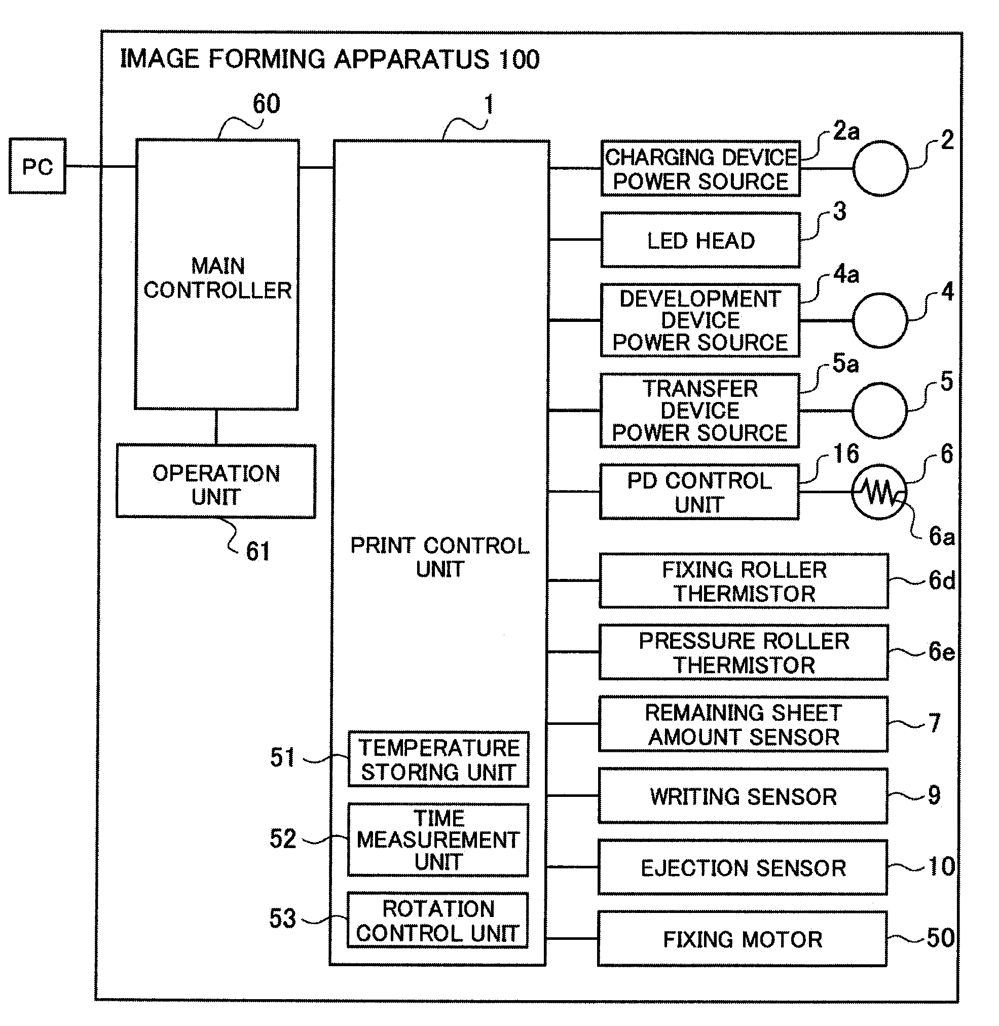
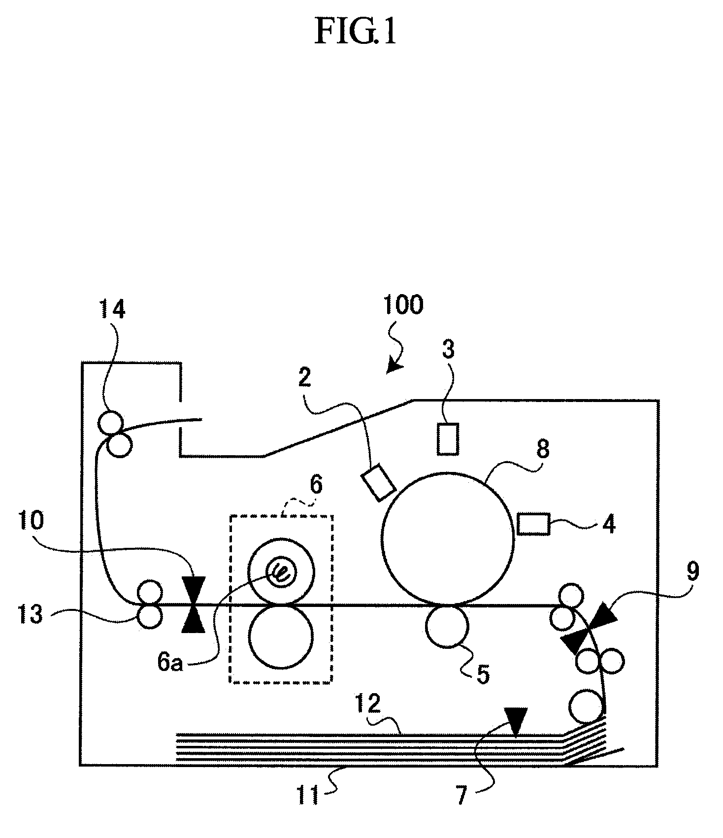
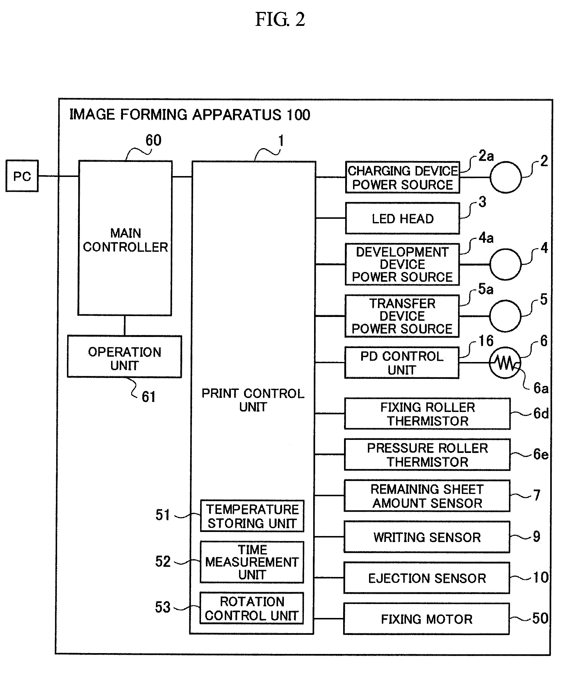
[0032]Referring to FIG. 1, an image forming apparatus 100 according to the present invention is illustrated. The image forming apparatus 100 includes a charging device 2, a light emitting diode (LED) head 3, a development device 4, a transfer device 5, a fixing device 6, a remaining sheet amount sensor 7, a photosensitive drum 8, a writing sensor 9, an ejection sensor 10, a sheet cassette 11, and ejection rollers 13 and 14.

[0033]Referring to FIG. 2, the image forming apparatus 100 is illustrated in a block diagram. The image forming apparatus 100 includes a print control unit 1 that includes a microprocessor, a read only memory (ROM), an electronically erasable and programmable read only memory (EEPROM), a random access memory (RAM), an input / output port, and a timer. The print control unit 1 is connected with an external information process apparatus such as a personal computer (PC) or an operation unit 61 (described later), and executes a print process by receiving a control signa...

second embodiment

[0060]Referring to FIG. 8, an image forming apparatus 200 according to a second embodiment of the present invention is illustrated in a block diagram. The image forming apparatus 200 is similar to the image forming apparatus 100 described above in the first embodiment except for a temperature comparison unit 54 that is disposed inside a print control unit 1. Components, configurations, and elements that are similar to those of the above embodiment will be given the same reference numerals as above and description thereof will be omitted. The image forming apparatus 200 halts rotation of a roller where a temperature variation amount to be calculated becomes smaller than a halt-threshold temperature variation amount, and where surface temperature of a fixing roller 6b becomes lower than threshold temperature.

[0061]The temperature comparison unit 54 compares temperature “T[n]” with threshold temperature “Tth_roll” to halt the rotation drive of the fixing roller 6b. The temperature “T[n...

third embodiment

[0070]Referring to FIG. 12, an image forming apparatus 300 according to a third embodiment of the present invention is illustrated in a block diagram. The image forming apparatus 300 is similar to the image forming apparatus 200 described above in the second embodiment except for a pressure temperature decision unit 55 that is disposed in a print control unit 1. Components, configurations, and elements that are similar to those of the above second embodiment will be given the same reference numerals as above and description thereof will be omitted. The image forming apparatus 300 halts rotation of a roller where a temperature variation amount to be calculated becomes smaller than a halt-threshold temperature variation amount, and where surface temperature of the fixing roller 6b becomes lower than threshold temperature to be arranged based on surface temperature of a pressure roller 6c.

[0071]The pressure temperature decision unit 55 stores information relating to the temperature of...


PUM


Abstract

An image forming apparatus forming an image by fixing a developer on a recording medium with heat includes a fixing member, a pressure member, a drive unit, a heat unit, a temperature detection unit, a control unit, and a temperature record storing unit. The fixing member is rotatably supported and heats the recording medium. The pressure member presses against the fixing member. The drive unit rotationally drives the fixing member. The heat unit heats the fixing member. The temperature detection unit detects temperature of the fixing member. The control unit controls the heat unit and the drive unit. The temperature record storing unit stores a temperature record of the temperature detection unit. The control unit controls, based on the temperature record of the temperature record storing unit, a rotation drive of the drive unit in a case of non-fixing.

Description

BACKGROUND OF THE INVENTION[0001]1. Field of the Invention[0002]The present invention relates to an image forming apparatus employing a fixing device.[0003]2. Description of Related Art[0004]An electrophotographic printer generally transfers toner corresponding to a print image to a sheet of paper and fixes the toner onto the sheet of paper with application of heat and pressure by a fixing roller and a pressure roller. In the course of a print process, heat of the fixing roller is removed from a surface thereof by a recording medium or the pressure roller. On the other hand, when passage of the recording medium is finished (i.e., the print process is finished), the heat is not removed, causing a rapid increase in surface temperature by emergence of the heat accumulated inside the fixing roller. Such a phenomenon is hereafter referred to as an overshoot. An excess increase in the surface temperature of the fixing roller causes poor fixing quality or damages of a fixing device. Japane...

Claims


Application Information

Patent Timeline
Patent Type & Authority Applications(United States)
IPC IPC(8): G03G21/20G03G15/20
CPCG03G15/2039
Inventor SATO, TOSHIKI
Owner OKI DATA CORP
Learn More