Cereal Bag Zipper

Inactive Publication Date: 2009-05-28
HICKEY IP
View PDF18 Cites 43 Cited by
  • Summary
  • Abstract
  • Description
  • Claims
  • Application Information

AI Technical Summary

Benefits of technology

[0014]According to one aspect of the present invention, a bag resealing system is provided that includes a resealable closure device. The resealable closure device is formed from a number of sections of a suitable and, preferably, a thermoplastic material that include a resealing mechanism with disengageable members on the opposed sections that operate to secure the sections to one another and selectively form an opening therebetween. The mechanism is also attached to a separate bottom or lower support strip that supports the resealing mechanism and includes an amount of an adhesive applied to the support strip opposite the disengagable members, which allows the closure device formed of the mechanism and the support strip to be adhered to the exterior of a bag, such as a plastic bag. The adhesive is covered by a release liner to avoid the inadvertent attachment of the adhesive to a substrate, such as a bag, until such time as it is desired to adhere the device to a bag. Once the resealable closure device is adhered to the bag using the adhesive on the support strip, due to the clearance provided between the bag and the mechanism by the inclusion of the support strip, the disengagable members of the mechanism can be separated without damaging the bag to expose an elongate guide opening formed in the support strip in alignment with the aperture defined between the disengageable members. After the mechanism has been opened, the bag is punctured along a line or at a location in alignment with the guide opening in the support strip, such that the aperture defined by the resealing mechanism is positioned directly over the opening formed in the bag along the guide opening in the support strip. This opening can be formed by an attachment to a shuttle or slider disposed on the resealable closure device that operates to simultaneously puncture and form a slit in the bag along the guide opening in alignment with the closure device, or can be formed using a cutting device completely separate from the resealable closure device. In this manner, the resealable closure device including the resealing mechanism and the support strip secured to the mechanism and including the guide opening can be utilized to form resealable closures on bags that are not manufactured with releasable closures in their original construction. Thus, the resealing system can be easily manufactured and utilized to retrofit a number of different unopened bag structures with a resealable closure mechanism.
[0017]According to still another aspect of the present invention, a resealable bag closure or zipper is provided that includes a base having an adhesive applied to one surface of the base, and opposed halves of a zipper closure secured in alignment with one another on the base opposite the adhesive. The halves of the zipper closure are secured to the base by another adhesive layer located between the zipper halves and the base. The base is U-shaped, with each half of the zipper closure secured to one side of the base and the sides of the base connected by a central section. The gap formed in the base between the opposed sides can be positioned over the opened portion or ends of the bag and has a width sufficient to enable the sides of the base on opposite sides of the gap to be positioned at least partially over opposite sides of the bag. Also, the central section of the base connecting the opposed sides of the base extends across the open end of the bag between the opposed sides of the open end of the bag to function to limit the extent to which the bag can be opened. Once the closure is secured to the bag, the items located within the bag can be dispensed through the opened portion of the bag and the closure, with the end of the bag forming a spout to assist in dispensing the items.

Problems solved by technology

This is often difficult to accomplish, because the material forming the bag is flexible and the opposed sides of the opening are hard to align with one another for the correct placement of the attachment flanges of the zipper strip along each side of the opening.
In addition, the zipper strip disclosed in the '373 patent cannot be positioned on bags prior to forming an opening in the bag.
Further, if the attachment surfaces are forced apart to provide sufficient clearance to form an opening, the engagement of the attachment flanges with immediately adjacent sections of the bag will result in tearing of the bag along lines not in alignment with the zipper strip, such that the zipper strip is no longer capable of providing a reclosable opening on the bag.
A large number of these types of containers or bags must be opened by severing, breaking or otherwise permanently deforming the container, such that the container cannot be re-closed after being initially opened.
This causes multiple problems with containers and bags of this type, not the least of which are the inadvertent spillage and / or premature spoilage of the contents of the container or bag.
Thus, once this seal has been opened to enable the contents of the bag to be dispensed, there is no manner or mechanism provided on the bag by which the bag can be subsequently closed to prevent spillage or spoilage of the contents of the bag.
However, these devices require that the clip be entirely removed from the bag in order to reopen the bag, consequently requiring that the clip be continually disengaged and re-engaged with the open ends of the bag.
Furthermore, as the clips are normally formed with two spring-biased arms, it is often difficult to properly position the arms with regard the open ends of the bag to effectively close the bag.
This problem is compounded by the fact that most clips of this type are formed with arms having a width less than that of the bag, such that the clip does not extend to the ends of the bag, even when properly engaged with the bag.
Thus, the use of these types of clips does not prevent the contents of the bag from inadvertently spilling out of the bag, or being spoiled due to an ineffective seal on the open end of the bag.

Method used


Image

  • Cereal Bag Zipper
  • Cereal Bag Zipper
  • Cereal Bag Zipper

Examples


Embodiment Construction

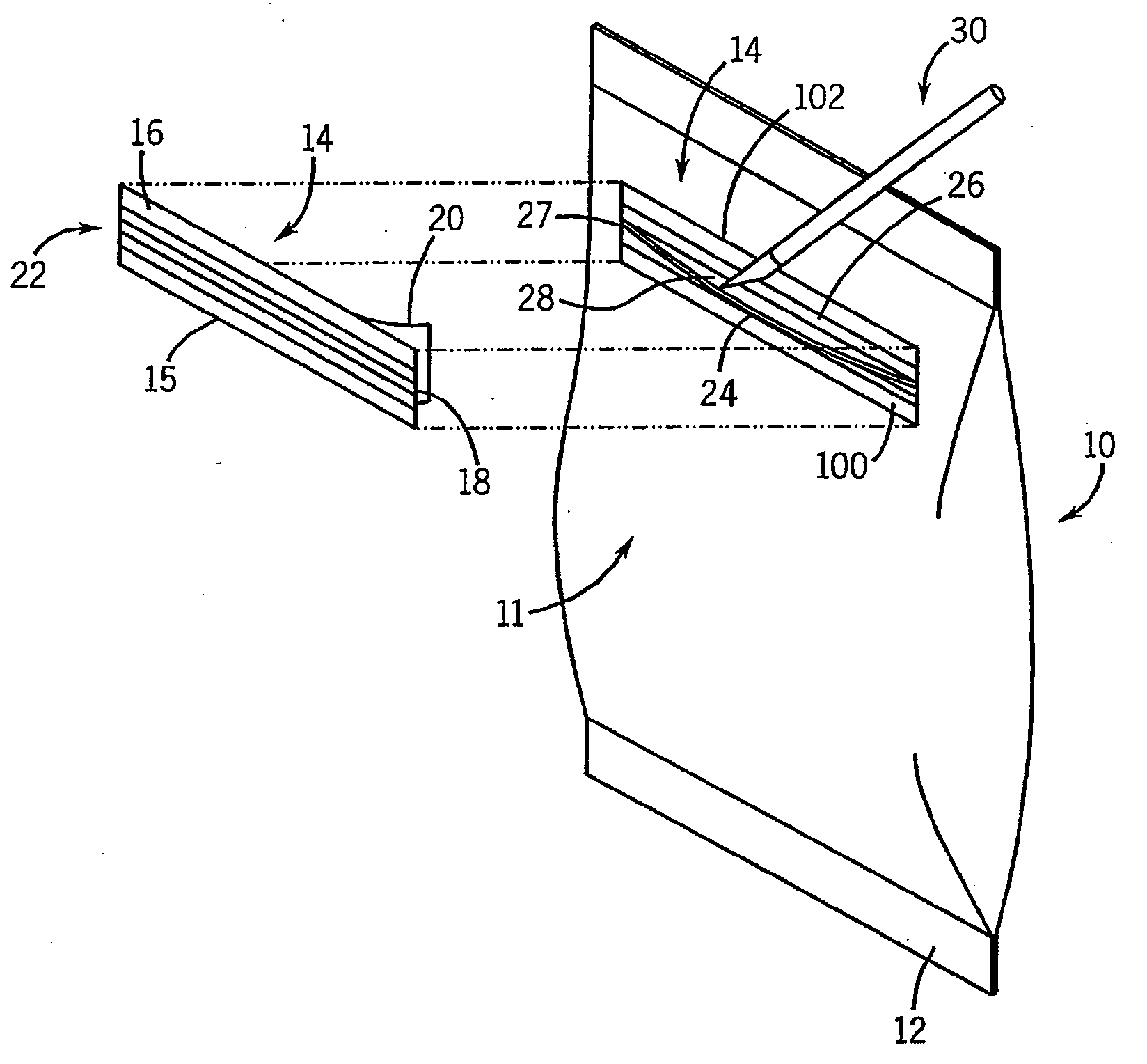
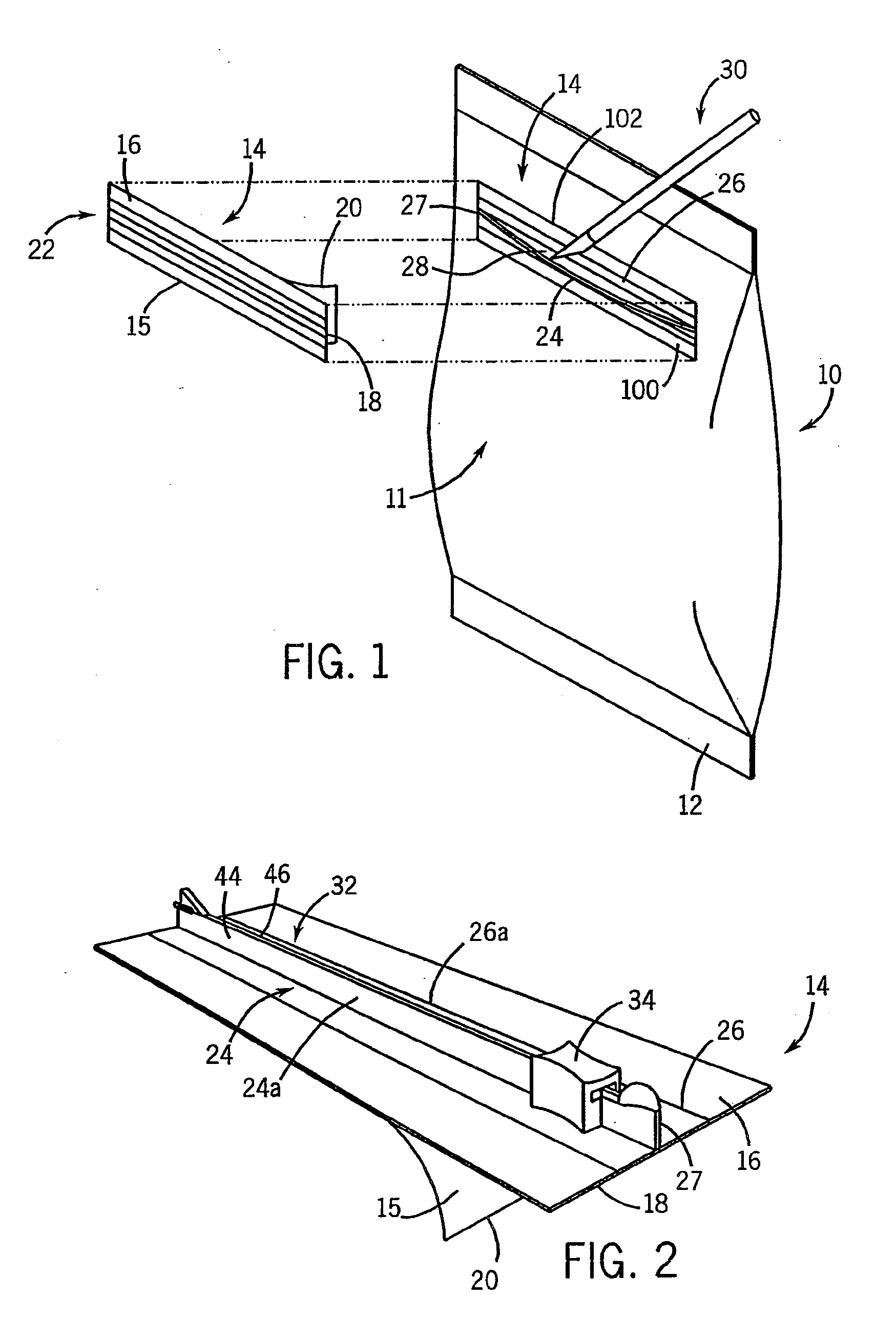
[0031]With reference now to the drawing figures in which like reference numerals designate like parts throughout the disclosure, a bag utilized to hold a number of items therein is illustrated generally at 10 in FIG. 1. The bag 10 can be formed of any suitable and easily severable material such as a plastic, paper, or metal foil material, and can have any desired construction that is utilized to hold the item(s) within the bag 10. In one embodiment illustrated in FIG. 1, the bag 10 is sealed at opposed ends 12 to enclose the interior of the bag 10 and hold a number of items therein. Between the sealed ends 12, the structure of the bag 10 has a generally continuous exterior 11 to securely hold the items within the bag 10.

[0032]To enable the bag 10 to be selectively opened and closed to gain access to the items held within the bag 10, a bag resealing system 14 constructed according to the present invention can be secured to the bag 10 at any point between the sealed ends 12. The syste...


PUM


Abstract

The present invention is a closure capable of being applied to an existing flexible container structure in order to form a releasable closure thereon. The closure includes base formed of a flexible material having an adhesive disposed on one side thereof in order to attach the closure to the exterior of a container. The closure also includes a pair of releasably engageable zipper sections secured to the base on opposite sides of a gap formed in the base having an open end and a closed end. The closure further has a liner located between the zipper sections and the base that extends over the gap to finction as a positioning device for properly locating the closure on the flexible container. The base and the liner also limit the size of any opening formed in the container to the size of the closure.

Description

CROSS-REFERENCE TO RELATED APPLICATIONS[0001]This application claims priority under 35 U.S.C. §120 as a continuation-in-part of U.S. Non-Provisional patent application Ser. No. 11 / 736,921 filed on Apr. 18, 2007, which in turn claims priority under 35 U.S.C. §119(e) from U.S. Provisional Patent No. 60 / 801,214, filed on May 17, 2006, and under 35 U.S.C. § 119(e) from U.S. Provisional Patent Application Ser. No. 60 / 988,514, filed on Nov. 16, 2007, each of which are incorporated by reference herein in their entirety.FIELD OF THE INVENTION[0002]The present invention relates to resealable closures and, more specifically, to a closure adapted to be positioned on and secured to or over an opening in a container, such as a cereal bag, to allow the container or bag to be selectively opened and resealed as necessary after being initially opened.BACKGROUND OF THE INVENTION[0003]Plastic and foil bags have long been utilized to hold a variety of items, including food products, therein for transpo...

Claims


Application Information

Patent Timeline
IPC IPC(8): B65D33/16
CPCB65D33/1691B65D33/2591B65D33/2583B65D33/2541B65D33/2508
Inventor HICKEY, CHARLES P.
Owner HICKEY IP
Why Eureka
Try Eureka