
3D inspection of an object using x-rays

a technology of 3d inspection and object, applied in the field of 3d inspection of objects using x-rays, to achieve the effect of keeping the cost of the system low and minimizing the use of computational electronics

Inactive Publication Date: 2009-05-28
SINGH SATPAL
View PDF7 Cites 8 Cited by
  • Summary
  • Abstract
  • Description
  • Claims
  • Application Information

AI Technical Summary

Benefits of technology

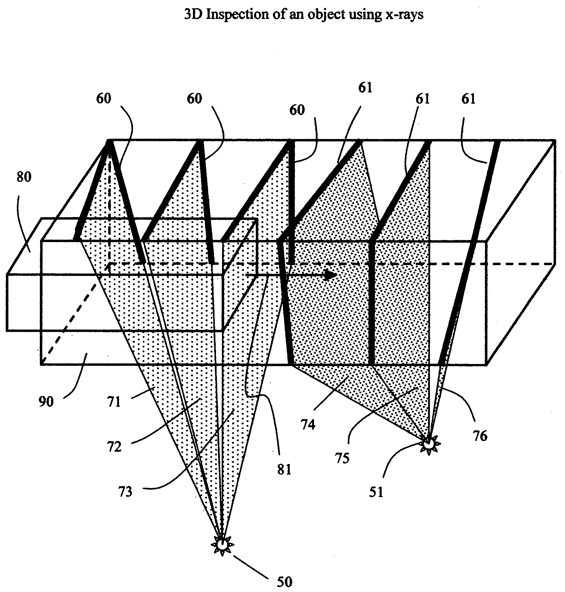
[0009]It is, accordingly, an object of the invention to provide a fast method of inspecting 3D volume of a scanned object or baggage, for example as required for the detection of explosives or contraband. It is also an object of the invention, to minimize the use of computational electronics and keep the cost of the system low.
[0012]This invention utilizes the fact that bombs and contraband to be detected have a finite size and therefore it is not necessary to reconstruct the image of the object in as detail as would be required for visual display of image, but only over a sparse set of points or pixels or voxels and analyzing at these points for the presence of explosives or contraband. This method of analyzing over only a sparse set of points reduces computational burden by orders of magnitude, greatly simply hardware and electronics design, and greatly speed up the scan time.
[0013]In one embodiment of this invention, the object or package is placed on a conveyor belt and moved through multiple fan beams of x-ray radiation, each fan beam being received and detected by a linear array of x-ray detectors. These fan beams are non parallel, that is they intercept the scanned object at different angles to produce multiple views of the objects from different angles. The data from these multiple views is then used according to the methods of back projection or any other suitable method of reconstruction well known to a person skilled in the art, to generate an image of a slice through the object. The novelty of this invention is that to save the computation time and complexity, the reconstruction is carried out only over a coarse grid. For example the slice image can be reconstructed over a grid of 256 by 256 pixels, or 65,536 pixels, however, the coarse grid according to this invention may be set only to 8 by 16 or 128 pixels. The idea behind this scheme is that explosives or bombs have a finite dimension which is usually larger than the fine grid of 256 by 256 required for visual display of even a low resolution image. For a bag with a cross section of 10 inches by 25 inches, a 256 by 256 grid would divide it into pixel size of 0.04 inches by 0.1 inch, where as any real bomb will have dimensions much larger than that. It is therefore adequate to only sample the cross section slice through the bag only over a spatial sampling distance larger than the minimum bomb size. This method of reconstructing only at a few sampled locations of the cross sectional slice saves the computation time and complexity by a huge factor, in the above example by a factor of 65,536 / 128=512.
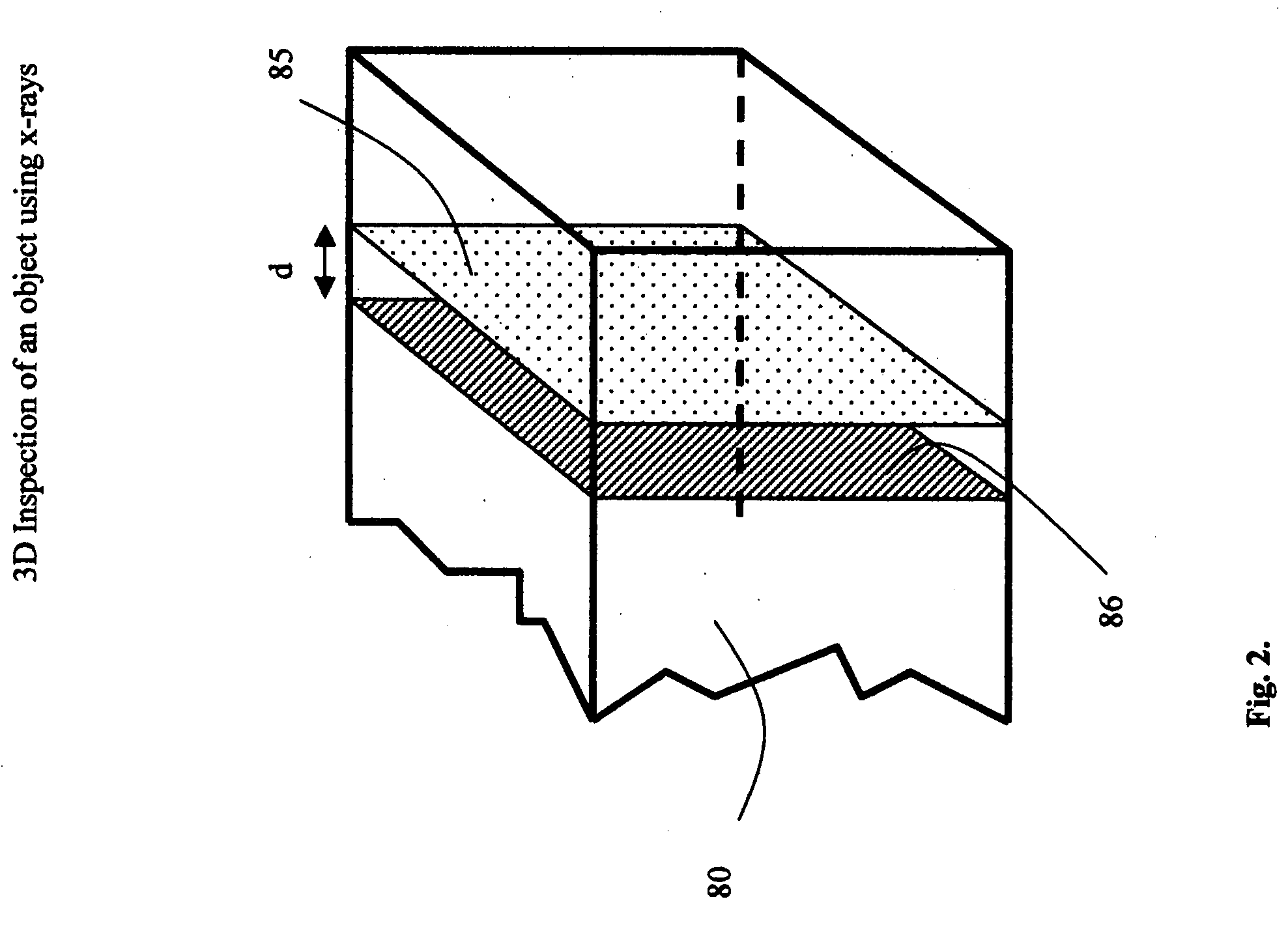
[0014]In another embodiment of the invention, the computational time can be further slashed by further reducing the number of sample points over which the reconstruction is carried out, for example, reconstructing over a grid of only 4 by 8 or a total of only 32 pixels. Compared to the original 256 by 256 grid, this results in a saving by a huge factor of 65,536 / 32=2048. However since the reconstructed grid of 4 by 8 is now very coarse, and there is a likelihood of missing the bomb, the reconstruction of the next cross sectional slice is carried out with the 4 by 8 grid offset diagonally to nearest diagonal pixel on a 16 by 32 grid. Reconstructing over 4 such diagonally offset consecutive or neighboring slices one can sample the object by a 16 by 32 grid which would be adequate for most small bags and parcels. The computational complexity is now much smaller and can be easily handled by personal computers. The idea behind reconstruction over offset slices is that a real bomb will have dimensions not only over a cross sectional slice, but also have sufficient dimensions of length.

Problems solved by technology

However since the reconstructed grid of 4 by 8 is now very coarse, and there is a likelihood of missing the bomb, the reconstruction of the next cross sectional slice is carried out with the 4 by 8 grid offset diagonally to nearest diagonal pixel on a 16 by 32 grid.

Method used


Image

  • 3D inspection of an object using x-rays
  • 3D inspection of an object using x-rays
  • 3D inspection of an object using x-rays

Examples


Embodiment Construction

[0021]In describing the preferred embodiment and its alternatives, specific terminology will be used for the sake of clarity. However, the invention is not limited to the specific terms so used, and it should be understood that each specific term includes all its technical equivalents which operate in a similar manner to accomplish similar purpose.

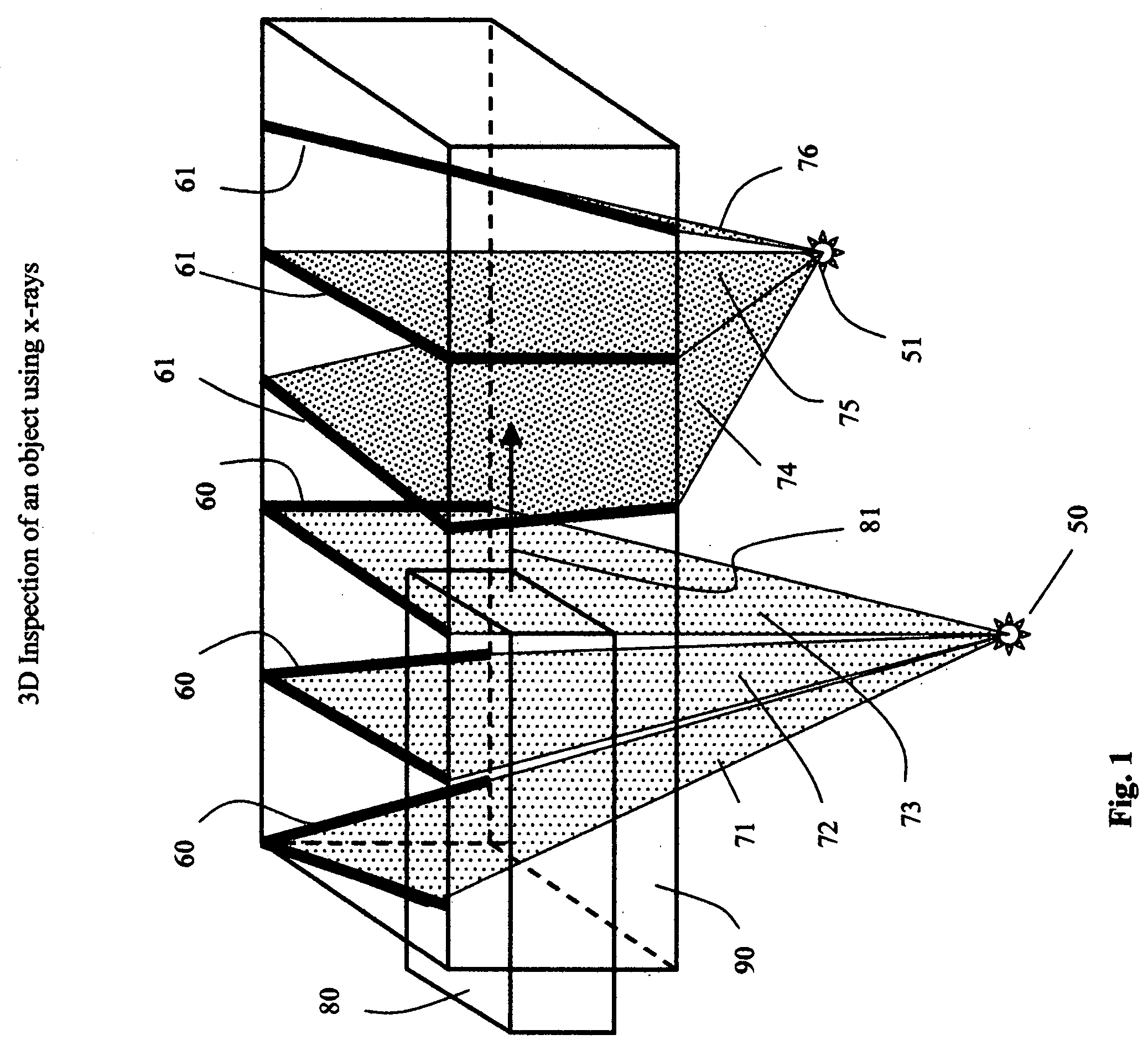
[0022]The technique described herein is applicable to any 3D imaging system, examples of which are, Computed Tomography implemented usually with a rotating gantry, Laminography, Tomosynthesis, and multi-view systems. For the sake of illustrating the application of the method of this invention, a multi-view system as described in U.S. application Ser. No. 11 / 399,443 (Singh) is described.

[0023]As shown in FIG. 1, an object or bag 80 is transported through a tunnel 90 in the direction of the arrow 81. Not shown in this figure to avoid the clutter are the conveyor belt, the motors and the transport mechanism and other details which are well kn...


PUM


Abstract

A method is presented for a 3D inspection of an object or bag in order to check for explosives or contraband. The method is applicable to Computed Tomography, Laminography or any other method that can be used to produce images of slices through the object. According to this method, it is not necessary to reconstruct the slice image with a high resolution as is required for visual display, but it is sufficient to reconstruct the image at only a sample or a set of points or pixels that are sparsely distributed within the reconstructed slice. The properties of the object are then analyzed only at these sparsely distributed pixels within the slice to make a determination for the presence or absence of explosives or contraband. This process of image reconstruction and analysis is repeated over several slices spaced through the volume of the object. In another embodiment of this invention, the set of points or pixels at which the image is reconstructed are offset spatially with respect to the set of pixels in the adjacent or neighboring slice. This invention greatly reduces the computational burden, hence simplifies the hardware and software design, speeds up the scanning process and allows for a more complete and uniform inspection of the entire volume of the object.

Description

CROSS REFERENCE TO RELATED APPLICATIONS[0001]This patent application is related to a co-pending U.S. application Ser. No. 11 / 399,443, “A Laminographic System for 3D Imaging and Inspection” (Satpal Singh), the contents of which are incorporated herein in their entirety by reference.BACKGROUND OF THE INVENTION[0002]1. Field of the Invention[0003]This invention relates to a 3D inspection of an object using x-rays, for example for detection of explosives or contraband in a package or baggage.[0004]2. Description of the Related Art[0005]Conventional baggage scanners generate a 2D image of the bag or object being scanned, they lack the 3D capability and are incapable of effectively checking for explosives.[0006]To overcome the above limitation of the conventional scanners, Computed Tomography (CT) systems were adapted from the medical world to scan for explosives in packages or baggage. CT though very effective, is a very complex system with a rotating gantry, is extremely slow, very bulk...

Claims


Application Information

Patent Timeline
Patent Type & Authority Applications(United States)
IPC IPC(8): G06T7/00
CPCG06T7/0004G06T2207/30112G06T2207/10116G06T7/0071G06T7/579
Inventor SINGH, SATPAL
Owner SINGH SATPAL
Learn More