
Spark plug for internal combustion engine and method for producing the spark plug

a technology for internal combustion engines and spark plugs, which is applied in the manufacture of spark plugs, spark plugs, machines/engines, etc., can solve the problems of deterioration of peel resistance, difficulty in making the distal end portion straight, and bending shape may still remain, so as to improve peel resistance and improve peel resistance. the effect of strength

Active Publication Date: 2009-05-28
NGK SPARK PLUG CO LTD
View PDF13 Cites 18 Cited by
  • Summary
  • Abstract
  • Description
  • Claims
  • Application Information

AI Technical Summary

Benefits of technology

[0010]The present invention was made in consideration of the above circumstances, and an object thereof is to provide a spark plug for an internal combustion engine capable of preventing deterioration in peel resistance, etc., of a noble metal tip due to the residual stresses caused by bending of a ground electrode. Particularly, the present invention has an object to prevent deterioration in the peel resistance upon considering a bulge portion which is formed to protrude by embedding a noble metal tip in a ground electrode and contains a same metal component as that of the ground electrode.

Problems solved by technology

Therefore, a bent shape may still remains at the distal end portion of the ground electrode (i.e., it becomes difficult to make the distal end portion straight), or stresses caused by the bending will remain.
If the spark plug is used while the residual stresses remains at the distal end portion of the ground electrode, the stress applied to the welded portion between the noble metal tip and the ground electrode may increase due to repetition of the cooling-heating cycle, and this may deteriorate a peel resistance of the noble metal tip.
Particularly, there is a need for a smaller diameter of spark plugs in recent years, and the diameter of the metal shell is also smaller, which may remarkably cause the above problem.
In addition, when the diameter of the metal shell is small, not only in a type in which a spark discharge is performed in the direction perpendicular to the direction of the axis line, the above problem is also found in a type in which a spark discharge is performed in the direction of the axis line.
However, in this case, strength at the bent portion cannot be secured, and another problem such as breakage of the bent portion may occur.

Method used


Image

  • Spark plug for internal combustion engine and method for producing the spark plug
  • Spark plug for internal combustion engine and method for producing the spark plug
  • Spark plug for internal combustion engine and method for producing the spark plug

Examples


Embodiment Construction

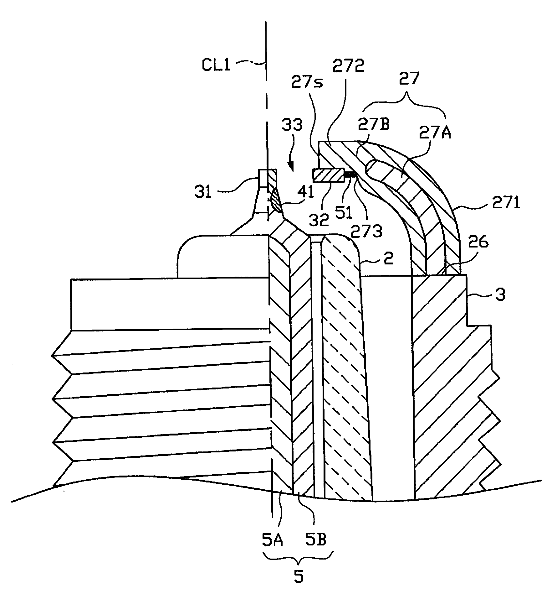
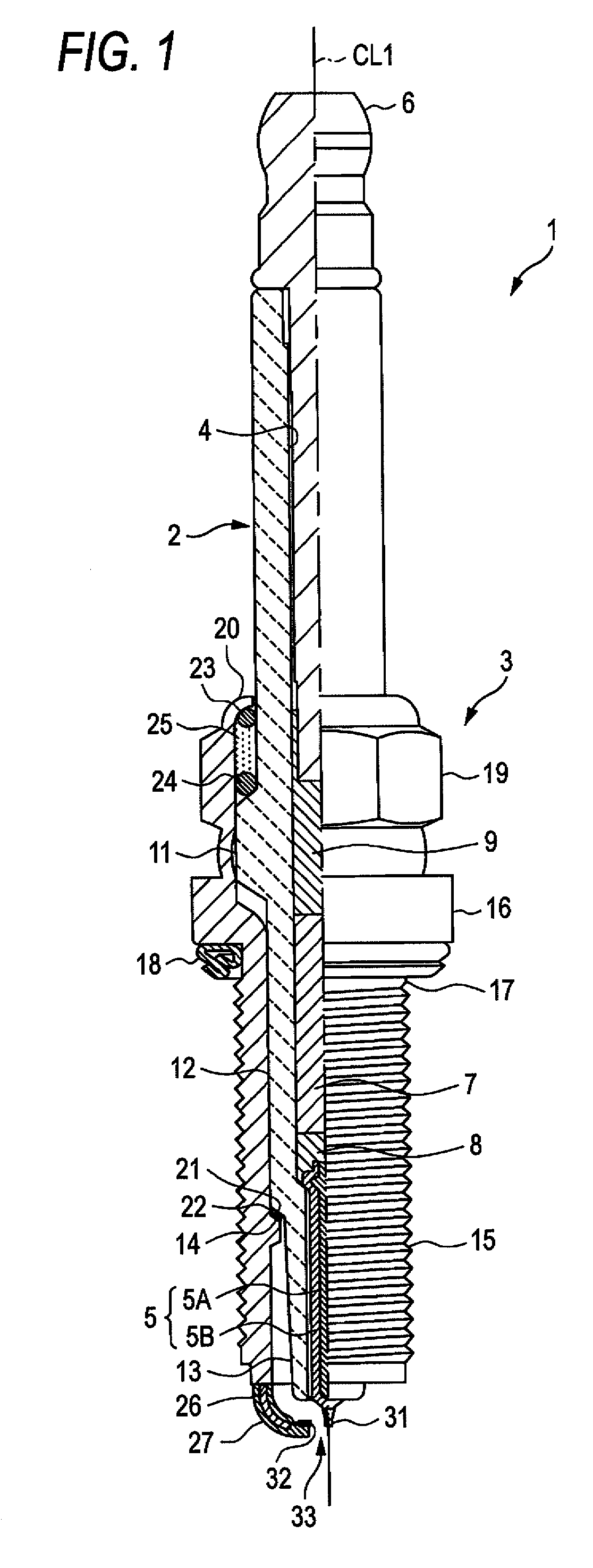
[0064]An embodiment of the present invention is described with reference to the drawings. However, the present invention should not be construed as being limited thereto. FIG. 1 is a partial sectional view of a spark plug 1. In the description, a direction of an axis line CL1 of the spark plug 1 (also referred to as an axial direction) corresponds to a vertical direction in FIG. 1. In addition a lower side in FIG. 1 corresponds to a leading end side of the spark plug 1, and an upper side in FIG. 1 corresponds to a base end side of the spark plug 1.

[0065]The spark plug 1 includes an insulator 2 serving as an insulating material and a cylindrical metal shell 3 holding the insulator 2.

[0066]The insulator 2 has an axial hole 4 penetrating therethrough along the axis line CL1. A center electrode 5 is inserted and fixed to the leading end portion of the axial hole 4, whereas a terminal electrode 6 is inserted and fixed to the base end portion thereof. A resistor 7 is disposed between the ...


PUM


Abstract

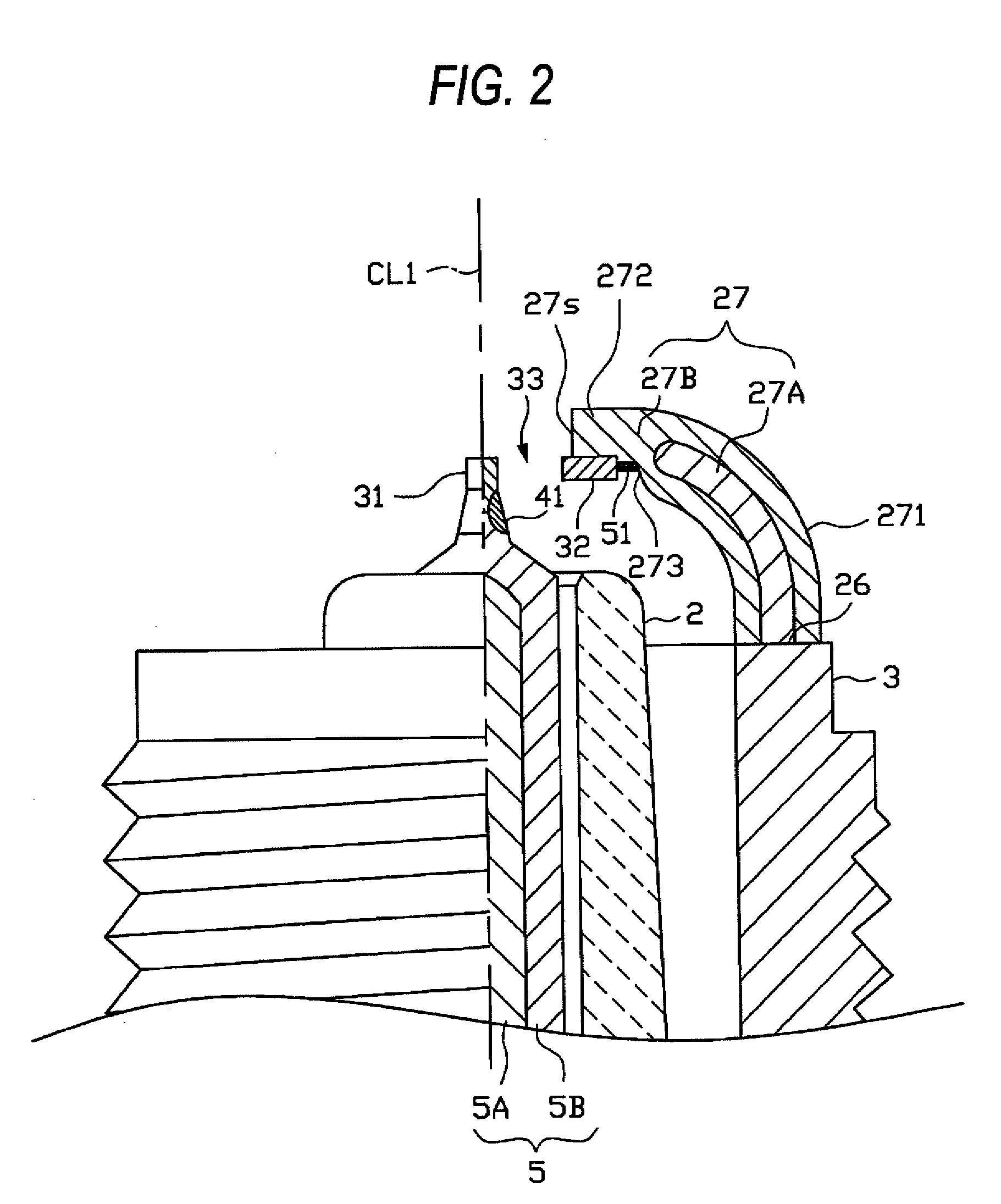
A spark plug including: a ground electrode including a thick portion provided on a base end side, a thin portion provided on a distal end side, and a stepped portion provided on an inner peripheral surface between the thick portion and the thin portion; a noble metal tip partially embedded in an inner peripheral surface of the thin portion; and a bulge portion provided on the inner peripheral surface of the thin portion between the stepped portion and the noble metal tip. When viewed from a side surface of the ground electrode, a relationship [a protruding height of the noble metal tip from the inner peripheral surface of the thin portion]≧[a protruding height of the bulge portion from the inner peripheral surface of the thin portion].

Description

BACKGROUND OF THE INVENTION[0001]1. Field of the Invention[0002]The present invention relates to a spark plug for an internal combustion engine and a method for producing the spark plug.[0003]2. Description of the Related Art[0004]A spark plug used for an internal combustion engine, such as an automobile engine, includes a center electrode extended in the direction of an axis line, an insulator disposed radial outside the center electrode, a cylindrical metal shell disposed radial outside the insulator, and a ground electrode having a base end portion joined to a leading end surface of the metal shell. The ground electrode has a substantially rectangular shape in cross section, and the inner side surface of the distal end portion thereof is bent to face the leading end portion of the center electrode. As a result, a spark discharge gap is defined between the leading end portion of the center electrode and the distal end portion of the ground electrode.[0005]In recent years, tips (no...

Claims


Application Information

Patent Timeline
Patent Type & Authority Applications(United States)
IPC IPC(8): H01T13/20H01T21/02
CPCH01T21/02H01T13/32
Inventor KAMEDA, HIROYUKINAKAYAMA, KATSUTOSHINAGASAWA, SATOSHI
Owner NGK SPARK PLUG CO LTD
Learn More