
Methods, devices and programs for transmitting roof and building structure of a 3D representation of a building roof based on said structure

Inactive Publication Date: 2009-05-21
FRANCE TELECOM SA
View PDF1 Cites 48 Cited by
  • Summary
  • Abstract
  • Description
  • Claims
  • Application Information

AI Technical Summary

Benefits of technology

[0021]Indeed, an embodiment of the invention proposes a technique relying on the use of procedural roof models constituting a simple and compact data transmission shape: indeed, each roof model is described by means of a type of roof (which may be encoded on only some bits, depending on the number of roof types envisaged), and one or more parameters, including a maximum height parameter. The volume of data needed for the transmission of each roof model is then relatively small.
[0022]Furthermore, these roof models are transmitted in an ordered list, the ordering of which defines their order of superimposition in the roof structure to be rebuilt. It is thus possible, by superimposition of different roofs of the list, to rebuild 3D representations of complex roofs, enabling a highly realistic rendering for the final user.
[0023]The technique of an embodiment of the invention therefore enables a resolving of the twofold technical problem of the compactness of data to be transmitted and the realism and complexity of the rebuilt roofs.
[0068]The obtaining of the ordered list may consist, for example, of a reception of this list transmitted by means of a communications network (such as the worldwide Internet network for example) or a loading of this list from a data carrier (of the CD-ROM or DVD type). This successive superimposition of the roofs of the list, by their truncation as a function of their maximum height, enables the rebuilding of complex roofs. Thus, by superimposing two gable roofs having distinct slope angles of the set of their sloping sides, it is possible to obtain a 3D representation of a curb roof. It may be recalled that a curb roof is a roof with two slopes, each of which is broken by an obtuse angle so that the lower slope is steeper than the upper slope.

Problems solved by technology

These different techniques however cannot be used to comply with the following constraints jointly:
Thus, the technique which consists of the transmission of a roof model, in VRML, in the form of a set of its faces generates a very large volume or even a prohibitively large volume of data in the case of complex roofs.
While, at reception, it enables the rebuilding of most shapes of roofs in a fairly realistic way, it is quite unsuited in the case of a town model which may contain several hundreds of thousands of buildings and for which the transmission time, through the network, of the set of 3D roof models will be considerable.
However, this technique does not enable the rebuilding of 3D depictions of hip type roofs, also called roofs with several sloping sides, wherein the sloping sides have the same slope angle relative to the horizontal.
This technique is therefore not suited to the depiction of models of real towns in which the buildings may have roofs of all types and especially complex gable roofs and hip roofs having a multiplicity of sloping sides.

Method used


Image

  • Methods, devices and programs for transmitting roof and building structure of a 3D representation of a building roof based on said structure
  • Methods, devices and programs for transmitting roof and building structure of a 3D representation of a building roof based on said structure
  • Methods, devices and programs for transmitting roof and building structure of a 3D representation of a building roof based on said structure

Examples


Embodiment Construction

[0107]The general principle of an embodiment of the invention relies on the transmission of a roof structure in the form of an ordered list of procedural roof models. Each roof model has a simple structure comprising types of roofs and one or more building parameters, inducing a small volume of data to be transmitted. Furthermore, these different roofs can be superimposed in the order defined by the list to rebuild a 3D representation of the real roof structure.

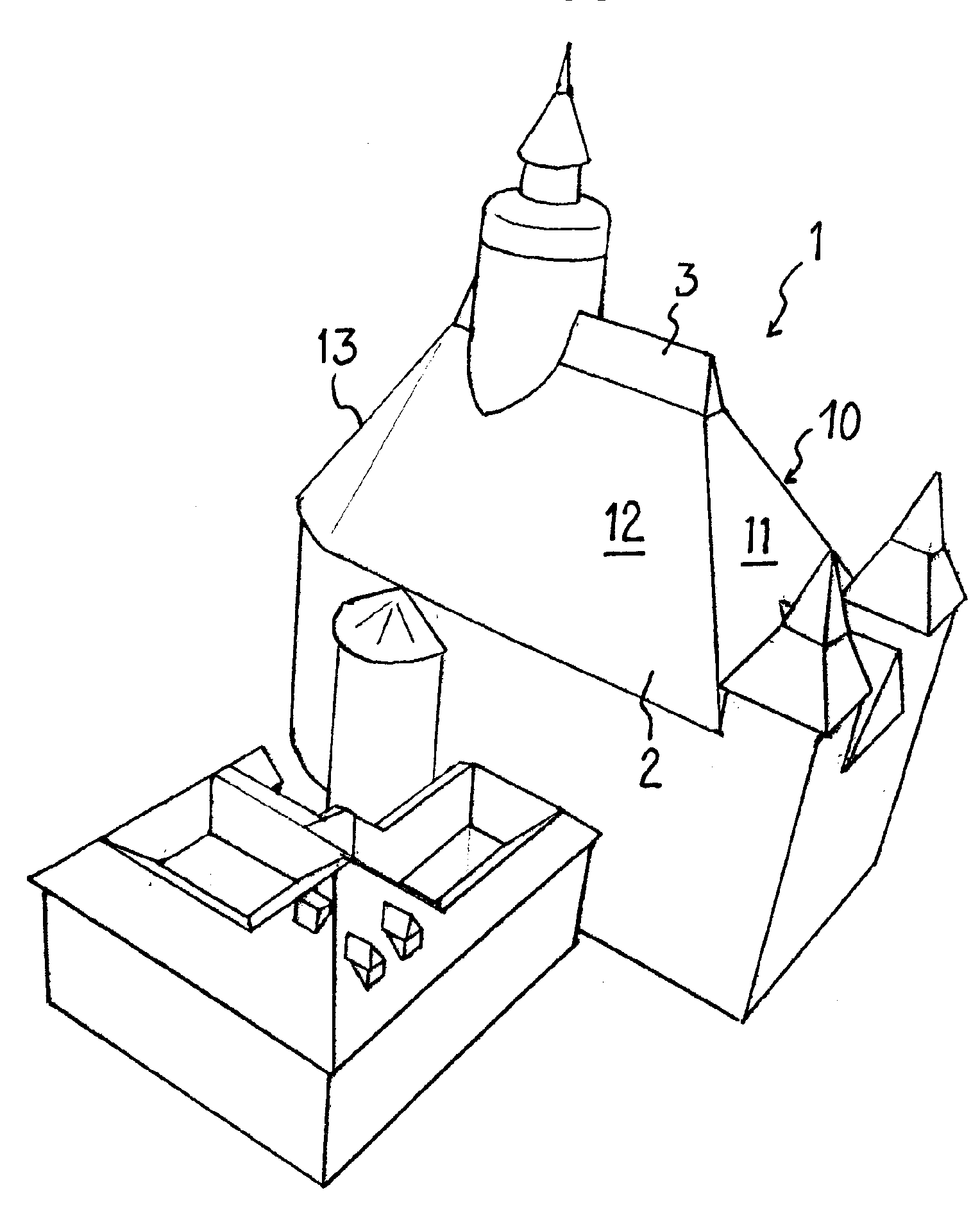
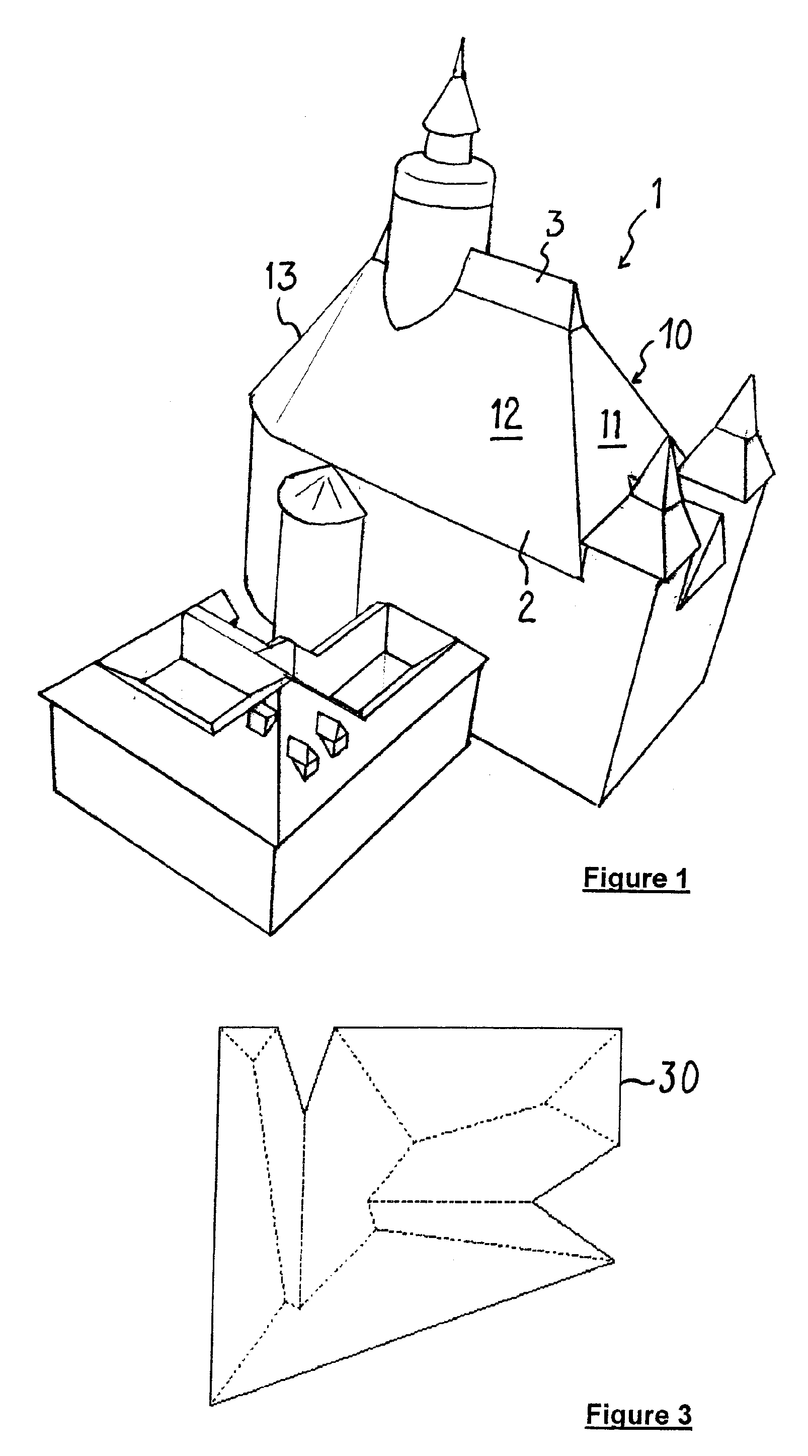
[0108]Referring to FIG. 1, an example is presented of complex roofs for which a 3D representation can be obtained according to a technique of an embodiment of the invention. FIG. 1 illustrates a church and the attached buildings. The roof 1 covering the nave of the church corresponds to the superimposition of two hip roofs: the lower hip roof 2 has three main slopes 10 to 12, a large number of smaller-sized sloping sides 13 above the choir of the church, to form the rounded portion of the roof; the sloping sides of the upper ...


PUM


Abstract

A technique is provided for transmitting a roof structure for constructing a three-dimensional representation of a building, via a communication network. The technique is based on the transmission of an ordered list of at least two roof models, each including at least: one type of roof; one maximum height parameter of the roof. During construction of the three-dimensional representation of a building, the maximum height parameter of a roof of the list determines a base of the roof in accordance with the list, so that the roof structure corresponds to the ordered superimposition of the roods of the list.

Description

CROSS-REFERENCE TO RELATED APPLICATIONS[0001]This Application is a Section 371 National Stage Application of International Application No. PCT / FR2006 / 002284, filed Oct. 11, 2006 and published as WO 2007 / 042667A1 on Apr. 19, 2007, not in English.FIELD OF THE DISCLOSURE[0002]The field of the disclosure is that of the visualization of three-dimensional images and 3D scenes. More specifically, the disclosure relates to a technique of data transmission enabling the visualization of such images or such scenes on a client terminal as well as the processing of this data at reception.[0003]It can be applied more particularly to the visualization of models of cities or urban scenes constituted by a set of buildings, and proposes a technique for the automatic reconstruction of roofs on the basis of the “eave gutter” contours of the buildings. It therefore enables the display, on a remote browser, of 3D models of buildings that is faithful to reality, with roofs of varying complexity.BACKGROUND...

Claims


Application Information

Patent Timeline
IPC IPC(8): G06T17/00G06T17/05
CPCG06T17/00
Inventor ROYAN, JEROMEGIOIA, PATRICKCAVAGNA, ROMAIN
Owner FRANCE TELECOM SA
Learn More