
Integrated nutplate and clip for a floating fastener and method of manufacture and assembly

a technology of floating fasteners and nut plates, which is applied in the direction of threaded fasteners, screwing devices, manufacturing tools, etc., can solve the problems of complicated and thus expensive milling of this type of structure in the backside of otherwise smooth interior structural components, and achieve the effect of being cheap and reliabl

Active Publication Date: 2009-05-21
RAYTHEON CO
View PDF0 Cites 8 Cited by
  • Summary
  • Abstract
  • Description
  • Claims
  • Application Information

AI Technical Summary

Benefits of technology

[0013]The present invention provides an inexpensive and reliable floating fastener.
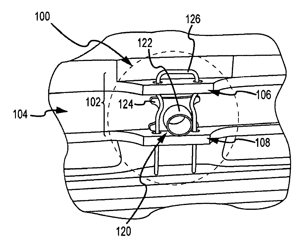
[0015]Milling this type of structure in the backside of an otherwise smooth interior structural member would appear to be complicated and thus expensive. However, high speed multi-axis milling machines allow the integrated nutplate to be milled virtually free, assuming a good design is selected. A ‘good’ nutplate design is one that provides the required torque resistance, facilitates the use of a simple clip to capture the nut and is efficient to mill. These requirements dictate that the nutplate include first and second discrete linear members each having at least one through-hole that is substantially perpendicular to the axial through-hole in the structural member. In an embodiment, the first and second discrete linear members are a pair of parallel rails milled on opposite sides of the axial through-hole. In many applications, the same pair of parallel rails can be used for multiple axial through-holes aligned in a linear configuration. The discrete linear members, e.g. parallel rails, lie along or parallel to an axis of the milling machine so that their formation does not slow the milling of the interior structural member.

Problems solved by technology

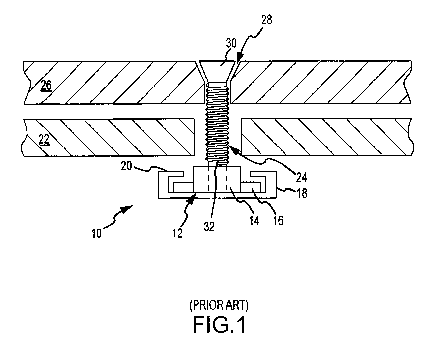
Milling this type of structure in the backside of an otherwise smooth interior structural member would appear to be complicated and thus expensive.

Method used


Image

  • Integrated nutplate and clip for a floating fastener and method of manufacture and assembly
  • Integrated nutplate and clip for a floating fastener and method of manufacture and assembly
  • Integrated nutplate and clip for a floating fastener and method of manufacture and assembly

Examples


Embodiment Construction

[0029]The present invention provides an inexpensive and reliable floating fastener by manufacturing an integrated nutplate into the backside of the interior structural member. A retention clip engages the nutplate to capture the nut while allowing the nut to float. The integrated nutplate roughly aligns the floating nut to the axial through-hole in the structural member and provides the torque resistance required to drive the screw into the nut. The retention clip holds the nut in place and provides the axial resistance required for the lead chamfer of the screw to engage the nut and resist the axial loading on the screw during installation. The nutplate is designed to facilitate cost-effective manufacturing. For Raytheon's JSOW the per hole cost is reduced from $6.75 for the MIL-spec standard riveted floating fastener to approximately $1.21. The JSOW includes 160 floating fasteners for a savings of approximately $886 per weapon. The exact per hole cost and total savings will vary d...


PUM


Abstract

An inexpensive and reliable floating fastener is provided by manufacturing an integrated nutplate into the backside of the interior structural member. A retention clip engages the nutplate to capture the nut while allowing the nut to float. The integrated nutplate roughly aligns the floating nut to the axial through-hole in the structural member and provides the torque resistance required to drive the screw into the nut. The retention clip holds the nut in place and provides the axial resistance required for the lead chamfer of the screw to engage the nut and resist the axial loading on the screw during installation. The nutplate is designed to facilitate cost-effective manufacturing. The per hole cost of the integrated floating-fastener is approximately 30% of the cost of the industry standard riveted floating fastener.

Description

GOVERNMENTAL LICENSE RIGHTS[0001]The U.S. Government has a paid-up license in this invention and the right in limited circumstances to require the patent owner to license others on reasonable terms as provided for by the terms of contract No. N00019-03-C-0001 awarded by Naval Air Systems Command.BACKGROUND OF THE INVENTION[0002]1. Field of the Invention[0003]This invention relates to floating fasteners and, more particularly, to the design, manufacture and assembly of a floating fastener having an integrally-formed nutplate and retention clip that provides the same reliable fastener installation at far lower cost.[0004]2. Description of the Related Art[0005]In many structural applications, structural members need to be fastened together. Oftentimes the structural members are too thin, too soft or otherwise too fragile to simply drive a screw through the members to form a reliable joint. Furthermore, misalignment of the structural members will exert a side loading on the screw that w...

Claims


Application Information

Patent Timeline
IPC IPC(8): F16B37/08B23P11/00
CPCF16B37/041Y10S411/97Y10T403/1683Y10T29/49947Y10T403/75Y10T29/49948
Inventor WOODALL, WAYNE K.POPE, WALTER S.ALTHOF, E. RUSSMUSE, SCOTT A.
Owner RAYTHEON CO
Learn More