
Digital signal receiving apparatus

Inactive Publication Date: 2009-05-21
AISIN SEIKI KK
View PDF2 Cites 3 Cited by
  • Summary
  • Abstract
  • Description
  • Claims
  • Application Information

AI Technical Summary

Benefits of technology

[0011]According to an aspect of the present invention, a digital signal receiving apparatus includes: an adaptive filter receiving a signal and adapted to switch between an adaptive mode for updating successively a filter coefficient thereof and for filtering out a correlated ambient noise from the signal by use of the filter coefficient and a non-adaptive mode for discontinuing updating of the filter coefficient and for filtering out the correlated ambient noise from the signal by use of the filter coefficient updated in the adaptive mode; a signal processing portion generating an auto-correlation signal based upon the received signal from which the correlated ambient noise is filtered out by the adaptive filter; a detection-judging portion having a first smoothing filter generating a first smoothed signal by smoothing the auto-correlation signal the detection-judging portion judging a possible presence of the desired signal in the signal when a signa

Problems solved by technology

In this case, the detection-judging portion may not judge detection accurately even in a signal receiving state, and may judge there is an absence of a detection of a desired signal.
Here, because the adaptive filter is not accurately controlled (switching control between an adaptive mode and a non-adaptive mode), the adaptive filter erroneously learns a desired signal as an ambient noise, thereby disabling to demodulate a desired signal accurately.

Method used


Image

  • Digital signal receiving apparatus
  • Digital signal receiving apparatus
  • Digital signal receiving apparatus

Examples


Embodiment Construction

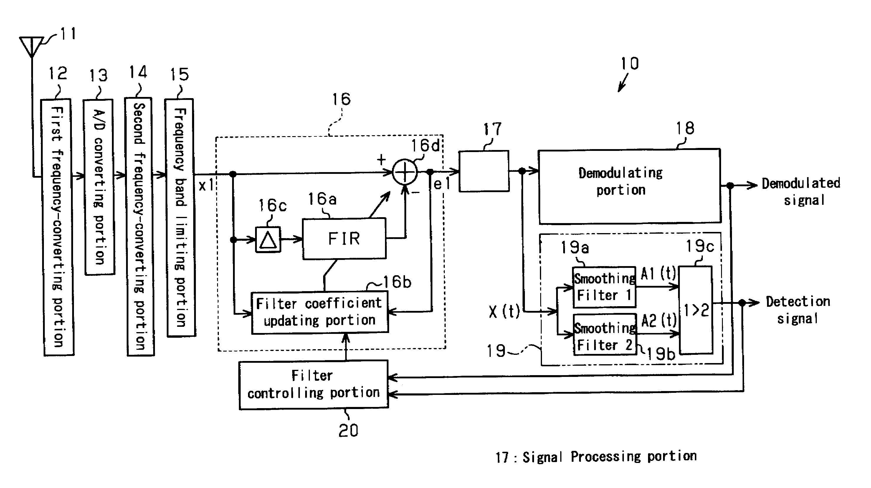
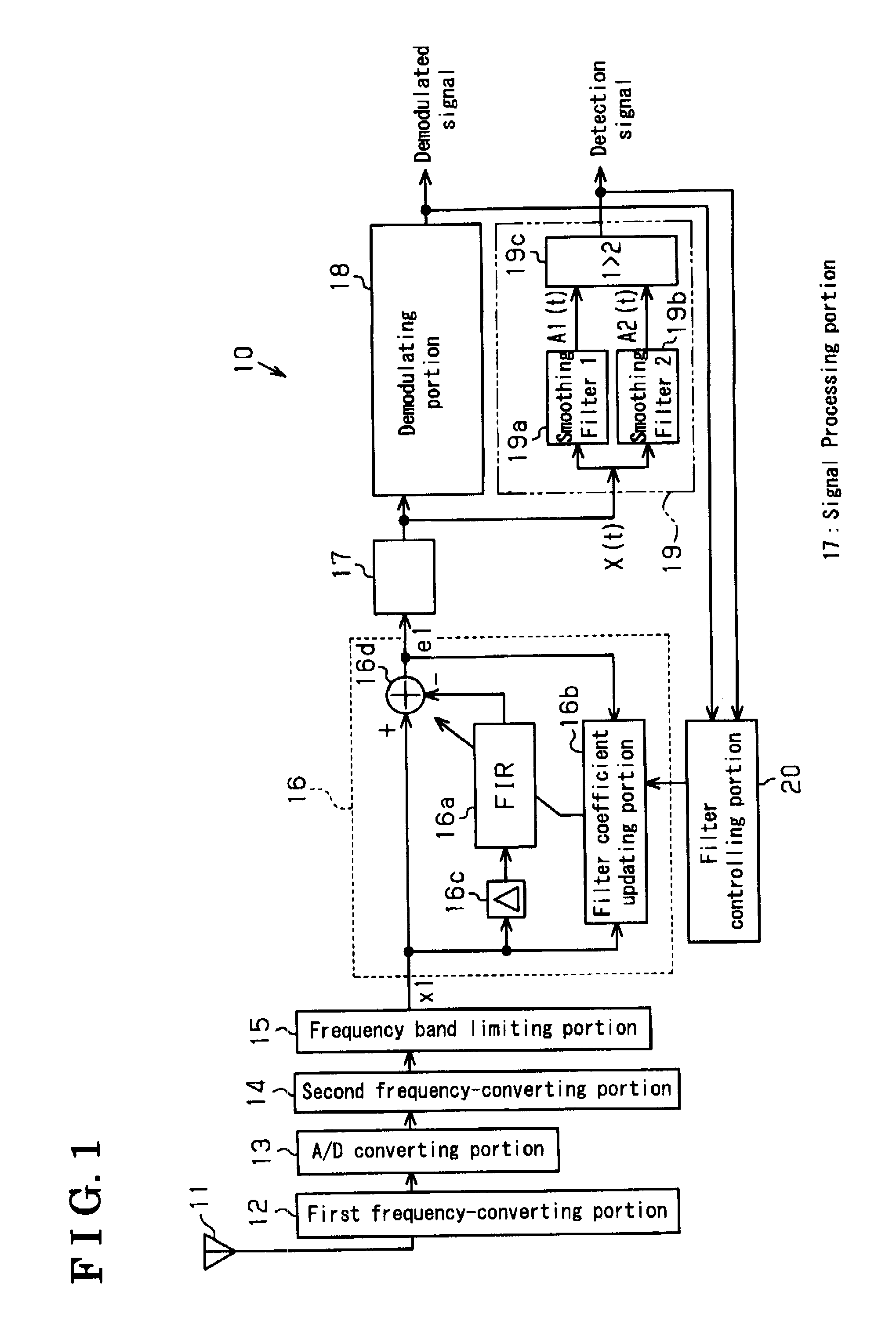
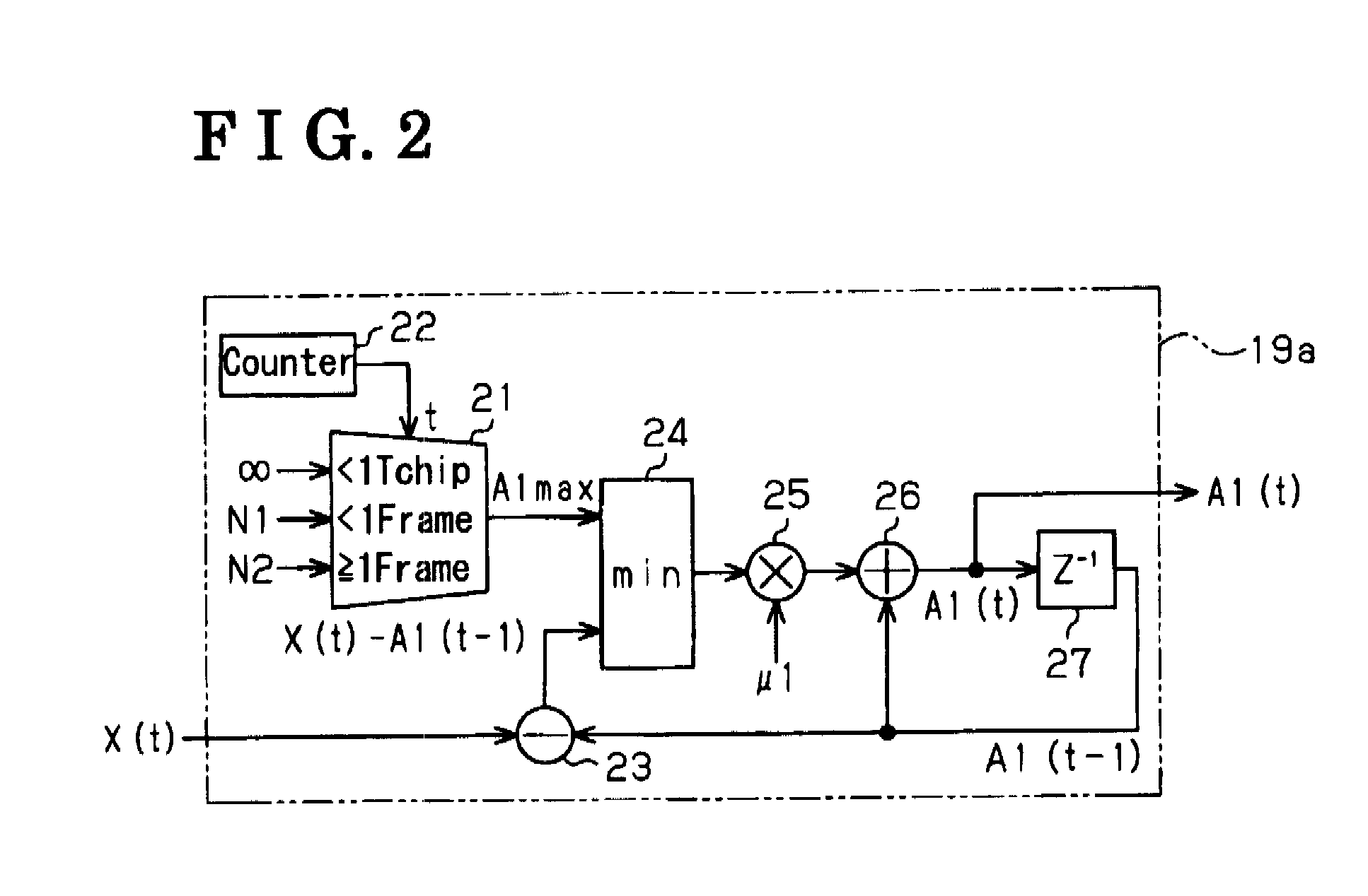
[0018]An embodiment of the present invention is described herein with reference to FIGS. 1, 2, 3 and 4.

[0019]FIG. 1 is a block view illustrating a system of an FSK (Frequency shift Keying) digital signal receiving apparatus 10. The FSK digital signal receiving apparatus 10 is configured to receive a signal, for example, transmitted from a transmitter carried by a user. The signal is hereinafter referred to as a desired signal. The FSK digital signal receiving apparatus 10 is switched between operation modes, which are a signal-receiving state, in which the apparatus 10 receives the desired signal, and a signal-receiving standby state, in which the apparatus 10 is in a standby state for receiving the desired signal.

[0020]As illustrated in FIG. 1, the FSK digital signal receiving apparatus 10 incorporates therein an antenna 11, a first frequency-converting portion 12, an A / D converting portion 13, a second frequency-converting portion 14, a frequency band limiting portion 15, an adapt...


PUM


Abstract

A digital signal receiving apparatus includes a detection-judging portion having a first smoothing filter generating a first smoothed signal by smoothing an auto-correlation signal and judging a possible presence of a desired signal when a signal level of the first smoothed signal is greater than a reference level and an absence of the desired signal when being smaller than the reference level. The smoothing filter includes a limiting portion limiting a fluctuation width of the first smoothed signal; and an adjusting portion configured to adjust the fluctuation width of the first smoothed signal limited by the limiting portion to be reduced while an elapsing time after the detection-judging means judges the possible presence of the desired signal is increasing.

Description

CROSS REFERENCE TO RELATED APPLICATION[0001]This application is based on and claims priority under 35 U.S.C 119 to European Patent Application No. 07120789.8 filed on Nov. 15, 2007, the entire of which is incorporated herein by reference.FIELD OF THE INVENTION[0002]The present invention relates to a digital signal receiving apparatus.BACKGROUND[0003]A known digital signal receiving apparatus is disclosed in Japanese Patent No. 2001-4736A (hereinafter, referred to as reference 1, see FIG. 4) for example. FIG. 5 is a block diagram illustrating a general configuration related to a digital signal receiving apparatus 70 disclosed in the reference 1. As illustrated therein, the digital signal receiving apparatus 70 receives a desired signal S contained with a correlated noise signal N as an ambient noise, by an antenna 71. Then, the digital signal receiving apparatus 70 down-converts the received signal to a desired frequency band at a high-frequency processing portion 72. Further, the di...

Claims


Application Information

Patent Timeline
IPC IPC(8): H04B1/10
CPCH04B1/123
Inventor YAMAMOTO, TOMOHIROFURUHASHI, AKIRAHORIE, TAKAHIROMURAKAMI, YUICHIONO, KAZUNORICOUTANT, FREDERICAOUINE, TARIK
Owner AISIN SEIKI KK
Learn More