Recording medium, reproducing apparatus, and reproducing method
a technology of reproducing apparatus and recording medium, which is applied in the field of recording medium, can solve problems such as the inability to decode other pictures
- Summary
- Abstract
- Description
- Claims
- Application Information
AI Technical Summary
Benefits of technology
Problems solved by technology
Method used
Image

Examples
first embodiment
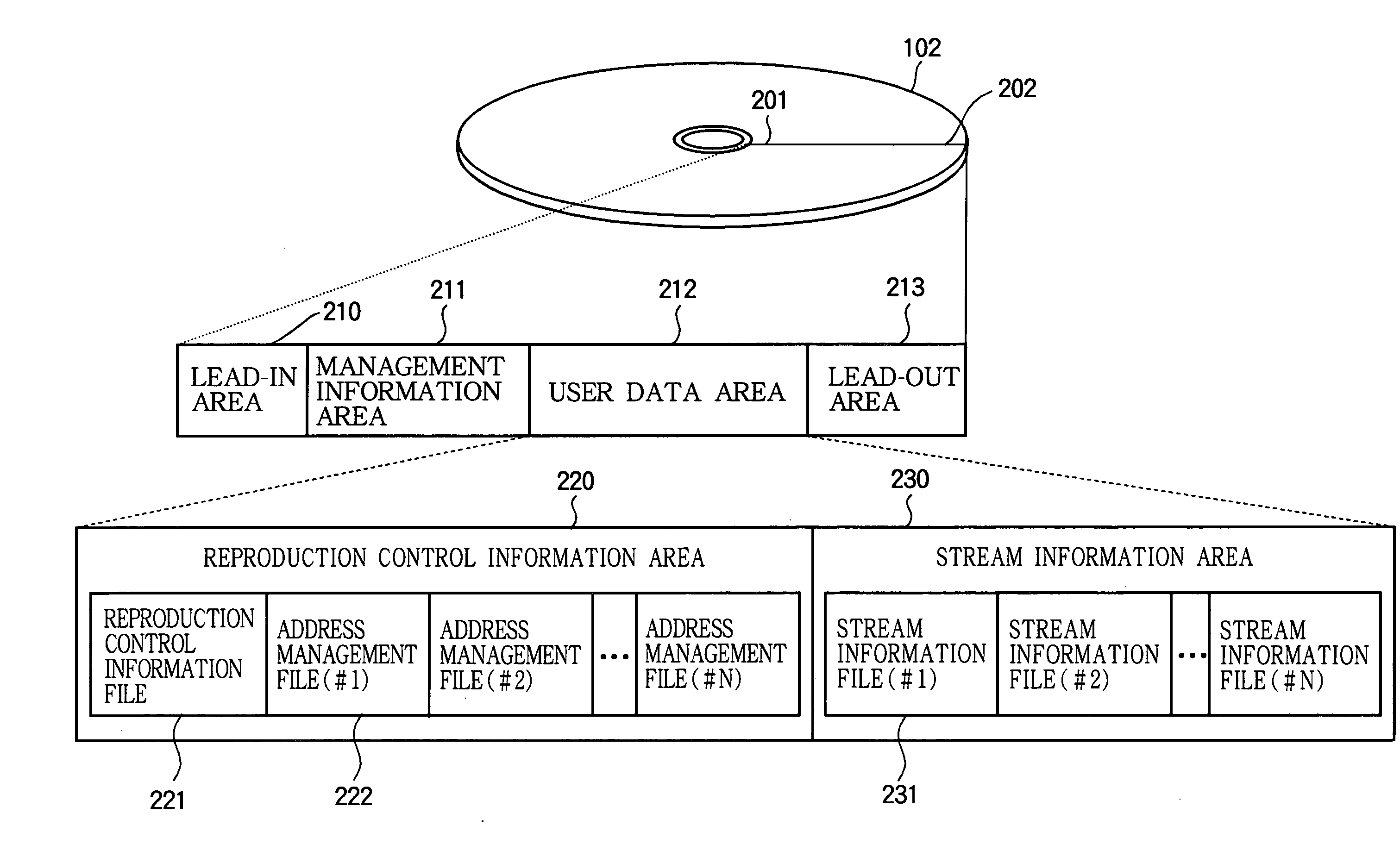
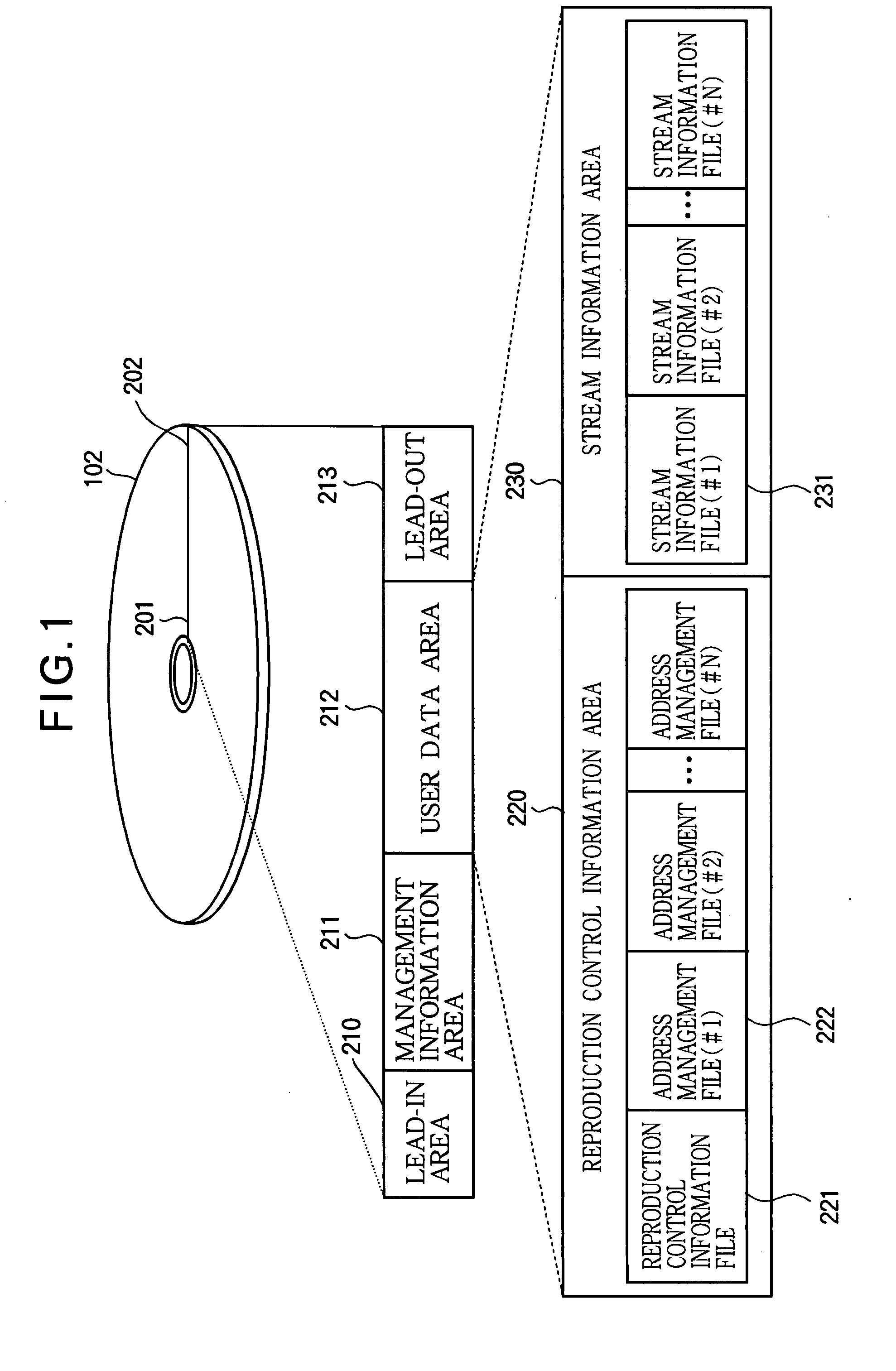
[0034]FIG. 1 is an explanatory diagram depicting the data structure of the optical disc 102 in the first embodiment of this invention. Data are recorded on the optical disc 102 from its inner circumference 201 to its outer circumference 202. A lead-in area 210 in which starting information about the optical disc 102, its physical characteristics, and the like are recorded is disposed at the innermost circumference of the optical disc. Information about the file system of the optical disc 102 (also referred to below as file system information) is recorded in a management information area 211 disposed just outside the lead-in area 210 of the optical disc 102. Content data (TS etc.) is recorded by the manufacturer (content provider) in a user data area 212 disposed just outside the management information area 211 in the optical disc 102. Information concerning the ending position of the optical disc 102 is recorded in a lead-out area 213 disposed just outside the user data area 212 of ...
second embodiment
[0103]In the first embodiment, the relative number of packets from the start of an access point is recorded in ‘I_Pic_Size’503, and the relative number of packets from the packet immediately following the packet corresponding to ‘I_Pic_Size’503 is recorded in ‘I_Pic_Size_Sub’1200. In the second embodiment, the information recorded in ‘I_Pic_Size’503 and ‘I_Pic_Size_Sub’1200 differs from that in the first embodiment. In the following description, explanations of matters explained in the first embodiment will be omitted.
[0104]FIG. 15 (A), FIG. 15 (B), and FIG. 15 (C) are explanatory diagrams showing other examples of the information recorded in ‘I_Pic_Size’503 and ‘I_Pic_Size_Sub’1200. FIG. 15 (A) schematically illustrates the relationship between a PIP stream 410 and the ‘I_Pic_Size’503 and ‘I_Pic_Size_Sub’1200 described in the first embodiment. FIG. 15 (B) schematically illustrates the relationship between the PIP stream 410 and the ‘I_Pic_Size’503 and ‘I_Pic_Size_Sub’1200 in the se...
third embodiment
[0122]In the first embodiment, a case was described in which the V_main packets in the main video stream and the V_sub packets in the sub video stream were detected for trick reproduction during a PIP display (FIG. 10 (B) or (C)). In the case to be described in the third embodiment, only the V_sub packets in the sub video stream are detected and only the sub video image is displayed (FIG. 10 (D)). In the following description, explanations of matters explained in the first and second embodiments will be omitted. In the drawings referred to in the following description, the unexplained elements are indicated by the same reference characters as in the drawings referred to in the descriptions of the first and second embodiments.
[0123]FIG. 16 is an explanatory diagram depicting the data structure of a stream information file 231 in which a PIP stream is stored and the data structure of the address management file 222 corresponding to the PIP stream according to the third embodiment. As ...
PUM
| Property | Measurement | Unit |
|---|---|---|
| video reproduction time | aaaaa | aaaaa |
| time | aaaaa | aaaaa |
| speeds | aaaaa | aaaaa |
Abstract
Description
Claims
Application Information
 - R&D
- Intellectual Property
- Life Sciences
- Materials
- Tech Scout
- Unparalleled Data Quality
- Higher Quality Content
- 60% Fewer Hallucinations
Browse by: Latest US Patents, China's latest patents, Technical Efficacy Thesaurus, Application Domain, Technology Topic, Popular Technical Reports.
© 2025 PatSnap. All rights reserved.Legal|Privacy policy|Modern Slavery Act Transparency Statement|Sitemap|About US| Contact US: help@patsnap.com