Constructive arrangement in a soft-starter

a technology of soft-starter and constructive arrangement, applied in the field of soft-starter, can solve the problems of high manufacturing cost, increased thermal resistance between, and the inability to suitably profit from the advantageous low thermal resistance of constructive arrangemen

Inactive Publication Date: 2009-05-14
WEG AUTOMACAO
View PDF13 Cites 3 Cited by
  • Summary
  • Abstract
  • Description
  • Claims
  • Application Information

AI Technical Summary

Benefits of technology

[0010]Therefore, an objective of the present invention is to provide a soft-starter having a new constructive arrangement which topology provides a substantial reduction of the dimensions of the soft-starter.
[0011]Another objective of the present invention is to provide a soft-starter having a new constructive arrangement that causes a low thermal resistance between the by-pass contacts and the heatsinks.
[0012]A further objective of the present invention is to provide a soft-starter having a new constructive arrangement that allows the contacts of the by-pass to operate in over-current condition without causing any damages to its construction.
[0013]Yet another objective of the present invention is to provide a soft-starter having a new constructive arrangement that provides a more robust configuration to the soft-starter, albeit its compact structure, that may support instantaneous overloads of the motor.

Problems solved by technology

However, in addition to not being compact this constructive arrangement is far more complex and therefore has a higher manufacturing cost.
The problem with this constructive arrangement is that it causes an increased thermal resistance between the by-pass contactor and the heatsink.
However, this constructive arrangement does not suitably profit from the advantageous low thermal resistance between the contactor and the heatsinks.
This is due to the fact that during the start of the motor the level of current in the SCRs is increased and the losses produce an increase in the temperature of the soft-starter.
The heatsinks can be used with natural or forced ventilation, which also interferes in the dimension of the soft-starter.
However, the contacts of the by-pass cause an increase in temperature while conducting the motor current, which is an additional drawback that has to be taken into consideration in-this constructive arrangement.

Method used


Image

  • Constructive arrangement in a soft-starter
  • Constructive arrangement in a soft-starter
  • Constructive arrangement in a soft-starter

Examples


Embodiment Construction

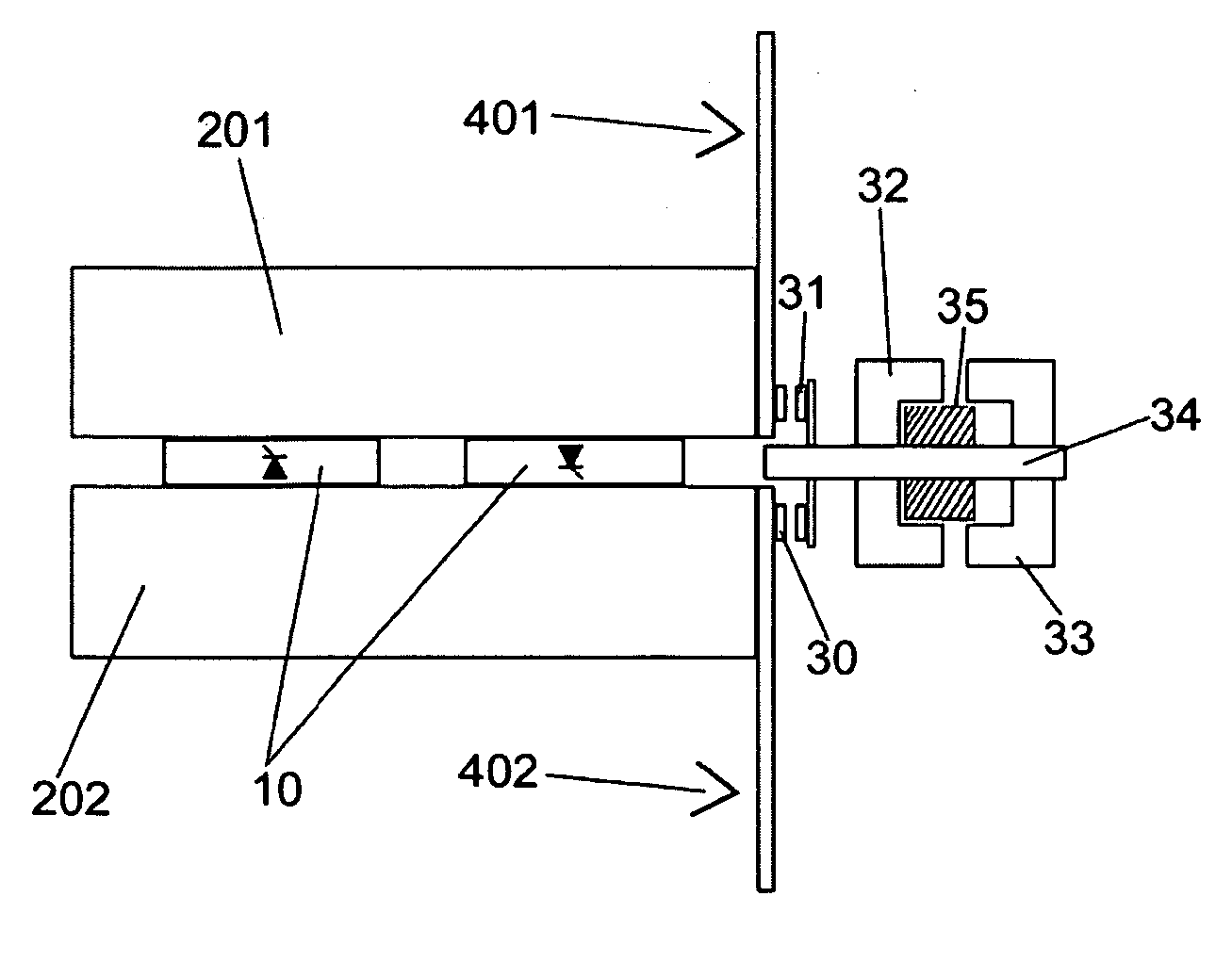
[0023]As it can be seen from the drawings, a soft-starter having a constructive arrangement according to the present invention comprises mounting the SCRs 10 and the contacts 30, 31 of the by-pass next to the heatsinks 201, 202, 203. By their turn, the heatsinks are interconnected to each other through a busbar 41, and are connected to the supply network through a busbar 401 and to the motor (not shown) through a busbar 402. The contacts 30, 31 of the by-pass are activated by a coil 35.

[0024]A magnetic field is formed when electric current passes through coil 35, which magnetic field pulls the plunger 33 of the coil against its fixed core 32. Therefore the contact carrier 34 of coil 35, which is attached at one of its ends to the plunger 33 and at its other end to the moveable contacts 31, is displaced together with the plunger 33 towards the fixed core 32 and simultaneously pushes the moveable contacts 31 in the direction of the fixed contacts 30, which are connected to the busbars...


PUM


Abstract

The present invention refers to a soft-starter having a new constructive arrangement comprising SCRs and a by-pass contactor connected through busbars that also provide an external connection to the soft-starter. The SCRs (10) and the contacts (30, 31) of the by-pass contactor are positioned next to the heatsinks (201, 202, 203), which by their turn are interconnected to each other by a busbar (41) and connected to the supply network by a busbar (401) and to the motor by a busbar (402), the contacts (30, 31) of the by-pass contactor being set in motion by a coil (35) activated by an electrical current.

Description

FIELD OF THE INVENTION [0001]The present invention refers to a soft-starter having a new constructive arrangement wherein the soft-starter is assembled with silicon controlled rectifier (SCR) stacks and by-pass contactors incorporated thereto.BACKGROUND OF THE INVENTION [0002]As it is known by those skilled in the art, a number of soft-starters having a by-pass contactor incorporated thereto are currently available in the market. These soft-starters are provided with SCRs that control the voltage applied to the induction motor during the start up or ramp down of the motor. Generally speaking, the SCRs are connected in an anti-parallel fashion (also known as a W1C connection) and the soft-starters may control one, two or three phases.[0003]One such type of soft-starter having a by-pass contactor incorporated thereto is shown in U.S. Pat. No. 6,531,940 B1, that discloses a soft-starter and contactors defined as two separate parts that can be assembled together. However, in addition to...

Claims


Application Information

Patent Timeline
IPC IPC(8): H02P1/00H01H50/00
CPCH02P1/30
Inventor BRAND, MARTIN
Owner WEG AUTOMACAO
Why Eureka
Try Eureka