
Linear pressure switch apparatus and method

a technology of linear switches and switches, applied in the direction of insulated conductors, cables, instruments, etc., can solve the problems of switching failures that require the removal and replacement of hard wired portions of the circuit, and the time-consuming and labor-intensive problem of individual application of linear switches

Inactive Publication Date: 2009-05-14
GRZAN JOHN T +2
View PDF23 Cites 2 Cited by
  • Summary
  • Abstract
  • Description
  • Claims
  • Application Information

AI Technical Summary

Benefits of technology

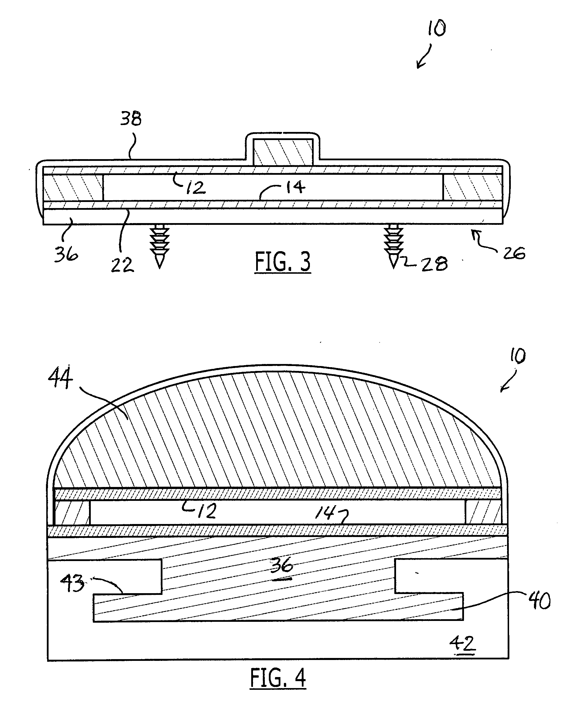
"The patent describes different versions of a linear pressure switch apparatus that includes a first and second elongate conductor plate separated by an insulative strip. The conductor plates have terminal end portions and the insulative strip provides electrical isolation between the plates. The switch is enclosed in a jacket that is at least water resistant. The switch can be attached to an external structure using a set of connectors. A bias member, such as a resilient foam, can be added between the jacket and the first conductor plate to provide a tactile sensation when activating the switch. The sensitivity of each pair of conductive plates can vary to provide a range of activation signals. The technical effects of this patent are improved durability and reliability of the linear pressure switch apparatus, as well as increased sensitivity and flexibility in providing activation signals."

Problems solved by technology

The problems associated with linear switches are well known and include those associated with coiling for transportation and storage as well as the ability to mass produce switches tailored for individual applications.
In particular, the tailoring of linear switches to individual applications can be a time consuming problem in which a section of linear switch is cut, spliced and hard wired into a circuit.
This connection between the conductors of the switch and circuit can become an additional reliability problem beyond that of the switch itself.
Further, the failure of the switch requires the removal and replacement of a hard wired portion of the circuit that is often further complicated by the use of a specialized channel or adhesive that attaches and fixes the switch to an external surface.
Specialized channels can fix linear switches in position and facilitate the activation of the switch, but these channels require additional fasteners to be installed and then a cumbersome and time consuming sliding integration of the linear switch and channel.
Another problem with linear switches is their lack of sufficient tactile sensation.
This raised backbone can facilitate switch actuation in many automated or industrial applications by providing a limited tactile sensation of the switch and direction for activating the switch, but locating and compressing the dense polymer or rubber materials along the narrow ridge can be difficult for many applications.

Method used


Image

  • Linear pressure switch apparatus and method
  • Linear pressure switch apparatus and method
  • Linear pressure switch apparatus and method

Examples


Embodiment Construction

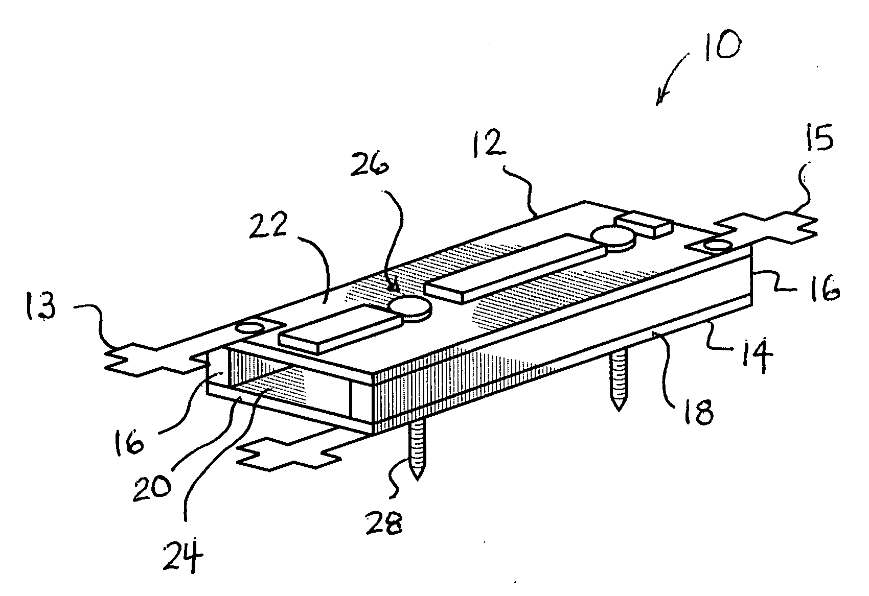
[0024]Referring initially to FIG. 1, linear pressure switch 10 is a parallel conductor continuous length switch that includes a first conductor 12 and a second conductor 14 positioned in spaced relation by insulation 16. Conductors 12 and 14 are conductive plates that preferably have an elongate shape with opposed longitudinal edges 18, opposed terminal end portions with lateral edges 20, an outward directed face 22 and an inward directed face 24. Conductors 12 and 14 can be made of any electrically conductive material, but are preferably made of spring steel. Linear switch 10 is a normally open momentary pressure sensitive switch.

[0025]Switch 10 is shown as an in-line switch with a first set of connectors 13 and a second set of connectors 15 that are adapted to interface with mating connectors. Connectors 13 and 15 are shown as standard spade connectors, but it is understood that connectors 13 and 15 can have any structure, angular orientation, positioning or configuration. Connect...


PUM


Abstract

A linear pressure switch is described that has two conductors separated by strips of insulation. The conductors are resilient members that can vary in thickness and material along with the insulation to provide a range of switch sensitivities. The switch can include connectors and an attachment mechanism that facilitates the installation and removal the switch from a given application. In addition, the switch can ergonomically enhanced actuation. The switches can be stacked in layers and selectively have different sensitivities to provide a desired signal output for each switch in a given application. The switch can also include external coatings on the jacket which enhance the feel and resistance of the jacket to wear and misuse.

Description

FIELD OF THE INVENTION[0001]The present invention relates to pressure activated linear switches and more specifically to improved pressure activated linear switch apparatuses that can be directly connected to an external surface, have ergonomic structures to facilitate activation and a range of external connector configurations.BACKGROUND OF THE INVENTION[0002]Linear switches have a broad range of applications that include mats that activate doors, electrical safety interrupts and automobile sensors. The problems associated with linear switches are well known and include those associated with coiling for transportation and storage as well as the ability to mass produce switches tailored for individual applications.[0003]In particular, the tailoring of linear switches to individual applications can be a time consuming problem in which a section of linear switch is cut, spliced and hard wired into a circuit. This connection between the conductors of the switch and circuit can become a...

Claims


Application Information

Patent Timeline
Patent Type & Authority Applications(United States)
IPC IPC(8): H01H3/14
CPCH01H2003/145H01H3/142
Inventor GRZAN, JOHN T.GRZAN, MATTMONTALTO, JOSEPH L.
Owner GRZAN JOHN T
Learn More