Eureka AIR delivers breakthrough ideas for toughest innovation challenges, trusted by R&D personnel around the world.

Subsea power umbilical

a technology of subsea power and umbilical cord, which is applied in the direction of cables, insulated conductors, borehole/well accessories, etc., can solve the problems of mechanical failure, power loss or heat, and disruption, and achieve the effect of reducing creep, reducing creep, and enhancing friction between the support member

Inactive Publication Date: 2009-05-14
CHEVROU USA INC
View PDF40 Cites 18 Cited by
  • Summary
  • Abstract
  • Description
  • Claims
  • Application Information

AI Technical Summary

Benefits of technology

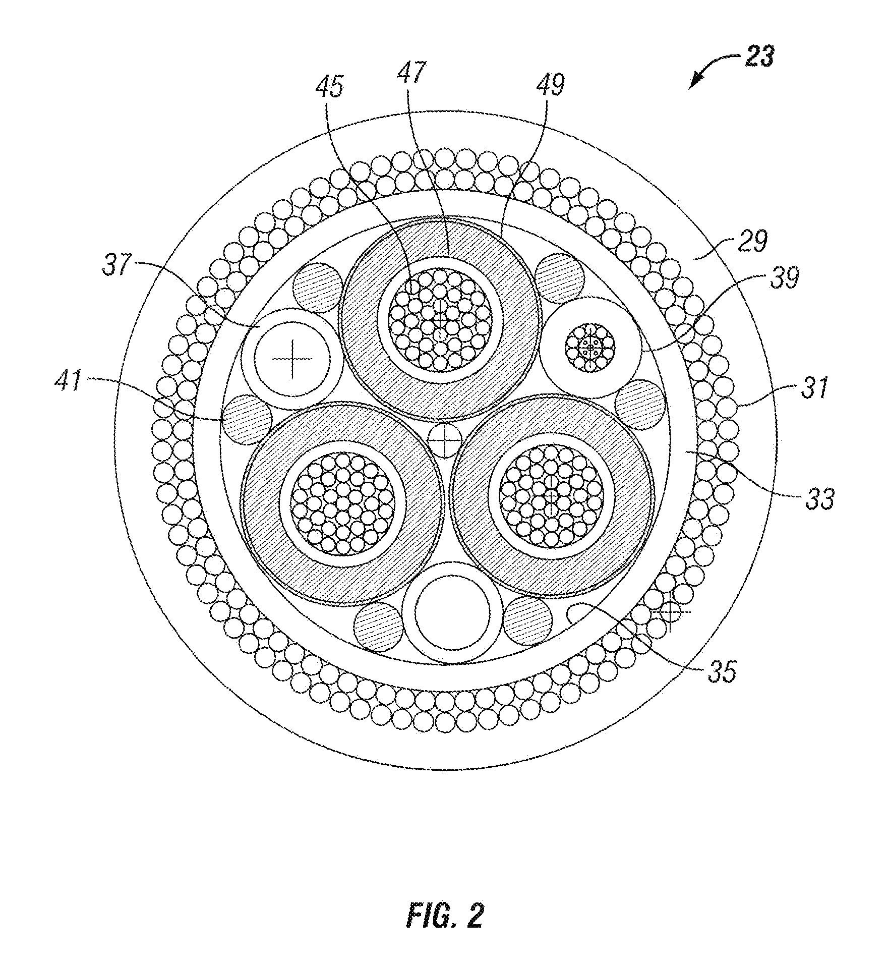
[0006]An umbilical assembly for supplying power to subsea equipment includes an electrical conductor to convey an electrical current to the subsea equipment. The umbilical assembly also includes an insulator surrounding the conductor. The umbilical assembly also has a support member, having either non-magnetic properties or low-magnetic properties, positioned between the insulator and the conductor. The support member is adapted to connect to a structure at the surface of the sea. The support member supports the weight of the conductor,
[0007]In the umbilical assembly, the conductor can be a stranded conductor. The stranded conductor can include copper or aluminum cables. When copper cables are used, the supporting of the weight of the conductor with the support member can reduce creep. In the umbilical assembly, the conductor can selected from a type of conductor consisting of a stranded conductor, a solid conductor, and a segmented conductor.
[0008]In the umbilical assembly, the support member can be close-coupled with the conductor. In the umbilical assembly, the support member can also have a textured inner surface that enhances friction between the support member and the conductor.

Problems solved by technology

Such deformation or creep can ultimately lead to mechanical failure because the copper can become stretched and embrittled.
However, even before such mechanical failure such deformation or creep creates losses with the electrical power being transmitted at the hangoff of the structure at the surface of the sea to the subsea equipment.
For example, the creep can cause power losses or heat which can be disruptive to the subsea equipment—such as motors for the subsea pumps, electrically submersible pumps, and compressors.
However, as the distance increases, such disruptions become larger and create a challenge because of the disruptions to the wave form of the electrical current.
Another problem that has been recognized with prior assemblies is hydrogen migration.
When such occurrence is unknown to the operator, the high pressure hydrogen has been known to blow connection the end of the umbilical with an explosion.

Method used


Image

  • Subsea power umbilical
  • Subsea power umbilical
  • Subsea power umbilical

Examples


Embodiment Construction

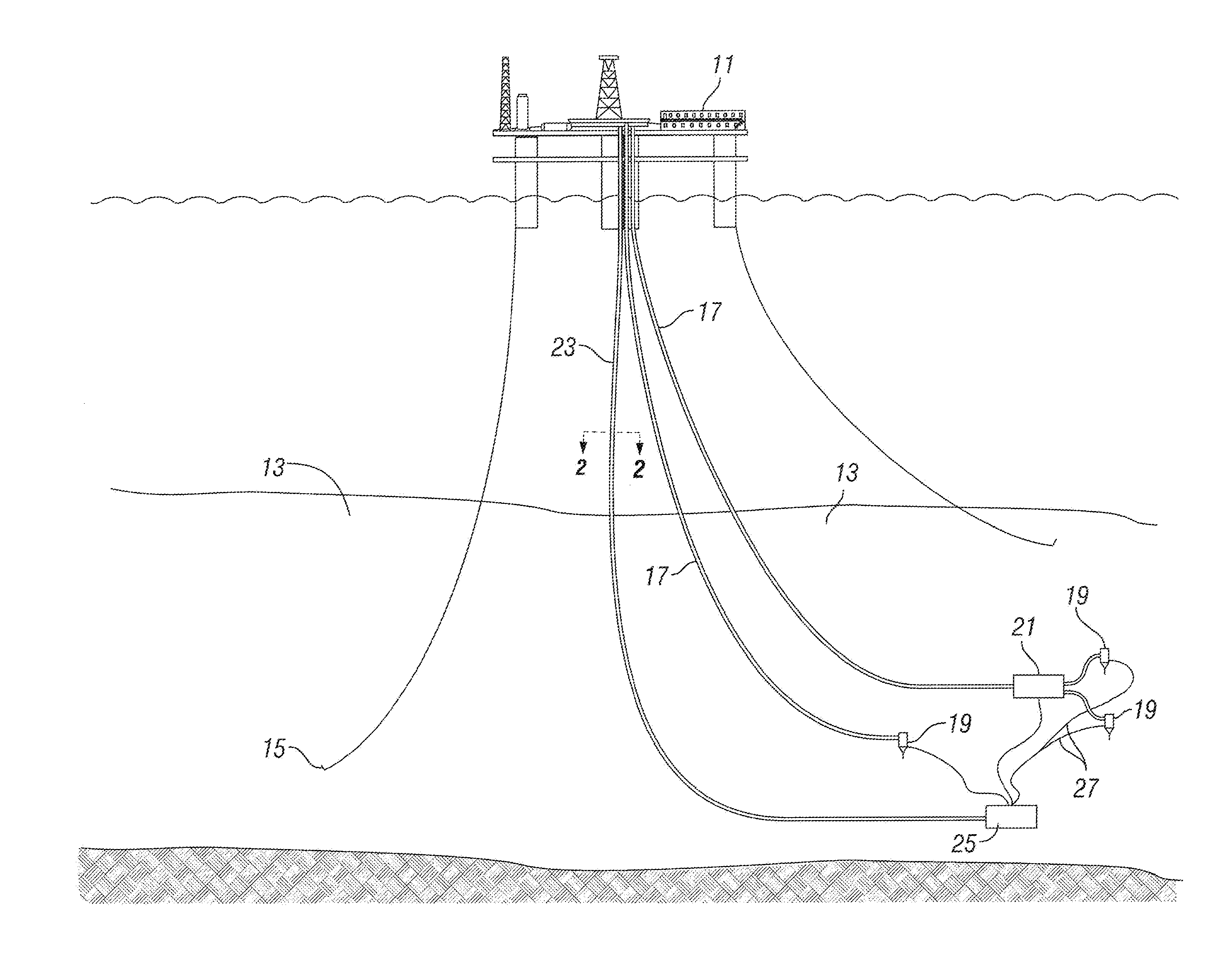
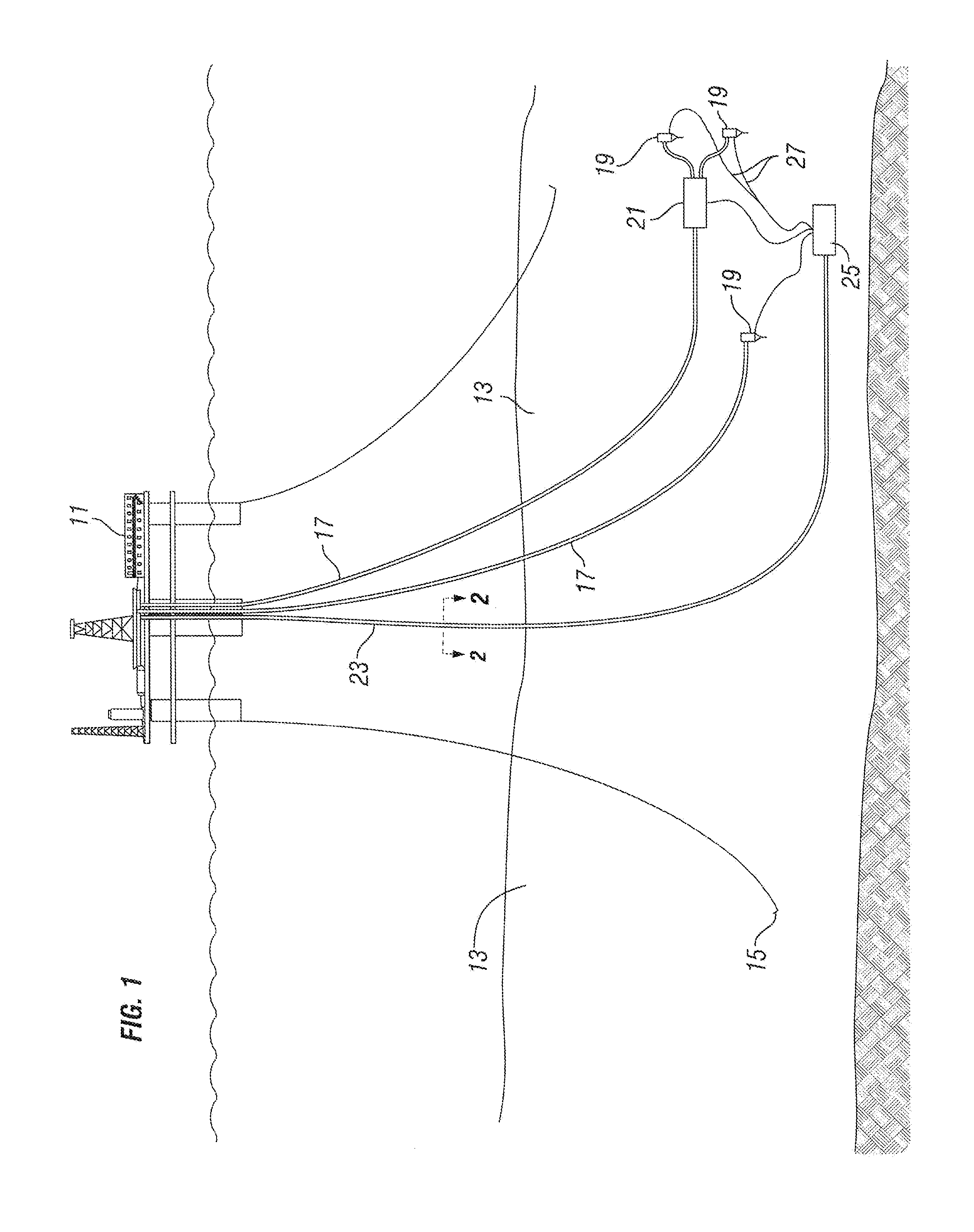
[0024]Referring to FIG. 1, a structure 11 is shown at the surface of the sea. Structure 11 is typically moored to a sea floor 13 by a plurality of mooring lines 15. While structure 11 is shown as a platform, it will be readily appreciated by those skilled in the art that structure 11 can alternatively be a floating production storage and offloading (FPSO) vessel. In an embodiment of the this invention, sea floor 13 is greater than or equal to 1500 feet deep such that structure 11 is supporting deepwater operations. In another embodiment of this invention, sea floor 13 is greater than or equal to 4000 feet deep such that structure 11 is supporting ultra-deepwater operations. As will be readily understood by those skilled in the art, “deepwater” and “ultra-deepwater” are terms of art which can vary slightly depending upon those you talk with and time. For the purposes of this invention, it is contemplated that these terms shall be as listed above.

[0025]A production riser 17 communicat...


PUM


Abstract

An umbilical assembly for supplying power to subsea equipment includes an electrical conductor to convey an electrical current to the subsea equipment. An insulator surrounds the conductor. A support member is positioned between the insulator and the conductor. The support member has either non-magnetic properties or low-magnetic properties because of its material composition. The support member is adapted to connect to a structure at the surface of the sea. The support member supports the weight of the conductor. The supporting of the weight of the conductor by the support member can be to reduce creep typically associated with the conductor supporting its own weight. The support member can be used to hermetically seal the conductor and prevent hydrogen migration along the conductor.

Description

TECHNICAL FIELD[0001]This invention relates to supplying electrical power to subsea equipment, and more particularly, to a power umbilical that can be used for supplying electrical power in deepwater and ultra-deepwater applications.BACKGROUND OF THE INVENTION[0002]In offshore hydrocarbon production, there is typically a structure either a vessel such as a floating production storage and offloading (FPSO) vessel or a platform-i, at the surface of the sea positioned above a production field on the sea floor. There are typically several wellheads that are producing hydrocarbons to be conveyed to the vessel. Moreover, there is often other subsea equipment that requires electrical power to control, regulate, pre-treat, and / or monitor the hydrocarbon production. For example, such equipment can include, but not be limited to, a subsea pump, a subsea compressor, a control or distribution module, a lower marine riser package and blow-out preventer, an electrically submersible pump, a subsea...

Claims


Application Information

Patent Timeline
Patent Type & Authority Applications(United States)
IPC IPC(8): E21B15/00
CPCH01B7/045
Inventor WORMAN, PETER J.TANJU, BAHA TULU
Owner CHEVROU USA INC
Why Eureka
Eureka Blog
Learn More