Rollover Judging Device
- Summary
- Abstract
- Description
- Claims
- Application Information
AI Technical Summary
Benefits of technology
Problems solved by technology
Method used
Image
Examples
embodiment 1
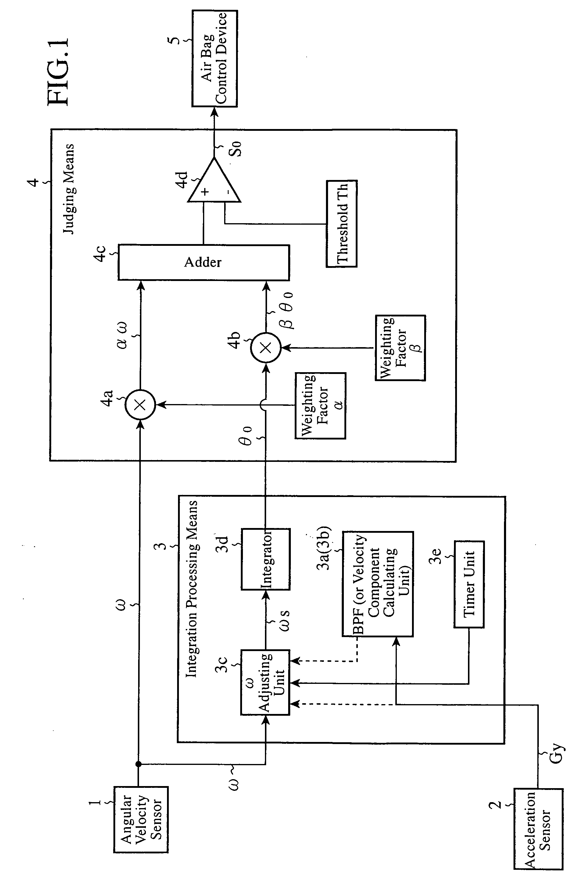
[0022]FIG. 1 is a block diagram showing the structure of a rollover judging device in accordance with Embodiment 1 of the present invention.
[0023]In FIG. 1, the rollover judging device in accordance with this Embodiment 1 is comprised of an angular velocity sensor 1, an acceleration sensor 2, an integration processing means 3, and a judging means 4. An air bag control device 5 is disposed as a next stage of this judging means 4.
[0024]In the above-mentioned structure, the angular velocity sensor 1 measures an angular velocity component of a vehicle in a direction of the vehicle's rollover, and outputs a signal showing the angular velocity A. This angular velocity sensor 1 is also called a roll rate sensor.
[0025]The acceleration sensor 2 measures at least either one of an acceleration component of the vehicle in a rightward or leftward direction of the vehicle and an acceleration component of the vehicle in an upward or downward direction of the vehicle. In the following explanation, ...
embodiment 2
[0141]FIG. 8 is a block diagram showing the structure of a rollover judging device in accordance with Embodiment 2 of the present invention. The same components as those shown in FIG. 1 are designated by the same reference characters, respectively.
[0142]The structure shown in FIG. 8 differs from that shown in FIG. 1 in that an integration processing means 21 is disposed instead of the integration processing means 3 of FIG. 1, and the other components are the same as those in the structure shown in FIG. 1.
[0143]The integration processing means 3 of FIG. 1 increases or suppresses the rate of the integration by adjusting the rate of the angular velocity ω, etc. on the basis of the occurrence pattern of the acceleration component Gy of the vehicle in its rightward or leftward direction which is measured by the acceleration sensor 2. In contrast, the integration processing means 21 of this FIG. 8 adjusts the amount of return which is used for integral value return-to-zero processing in a...
embodiment 3
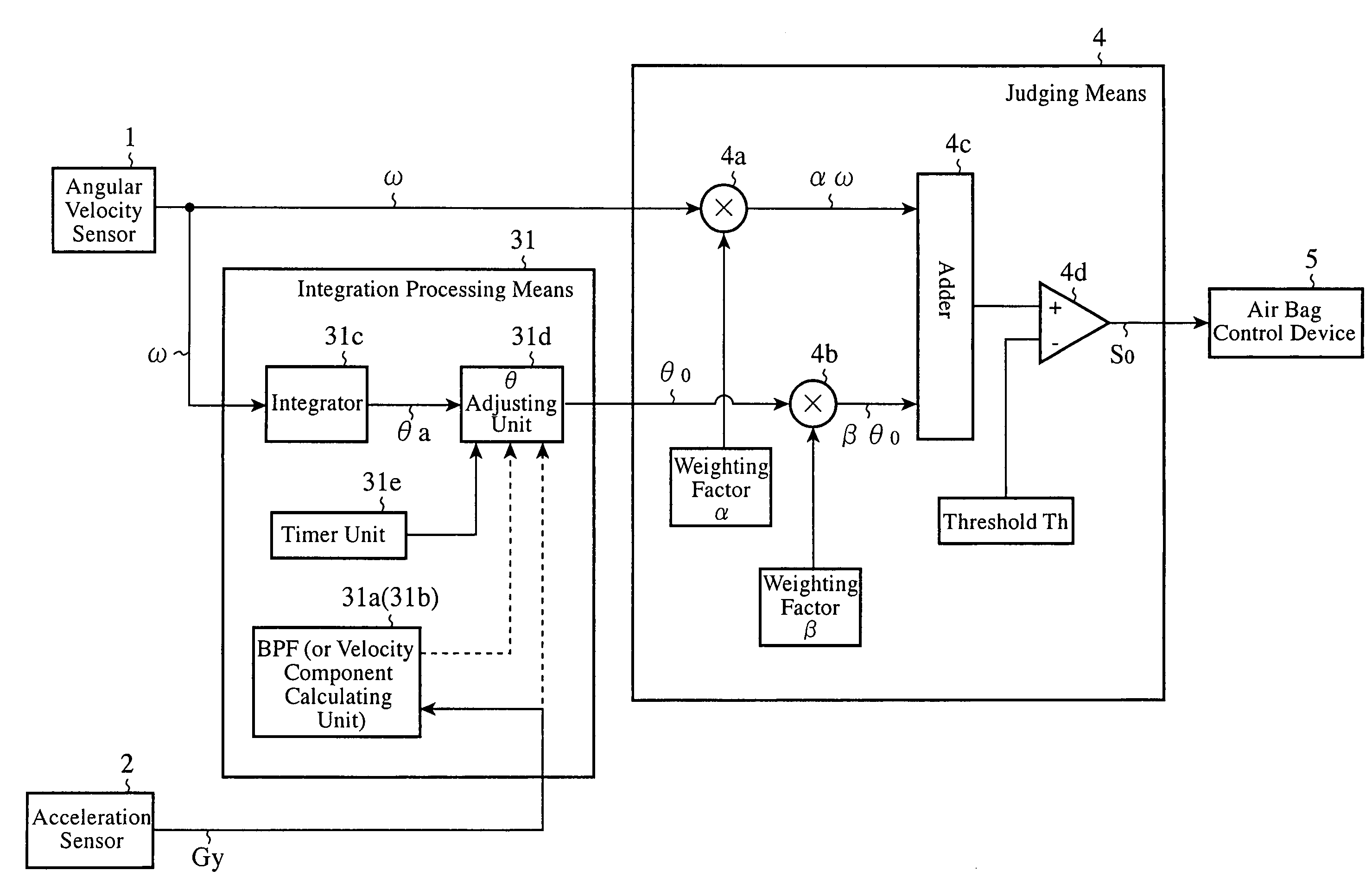
[0198]FIG. 10 is a block diagram showing the structure of a rollover judging device in accordance with Embodiment 3 of the present invention. The same components as those shown in FIG. 1 are designated by the same reference characters, respectively.
[0199]In FIG. 10, the structure shown in this figure differs from that shown in FIG. 1 in that an integration processing means 31 is disposed instead of the integration processing means 3 of FIG. 1, and the other components are the same as those of the structure of FIG. 1.
[0200]The integration processing means 31 of this FIG. 10 adjusts an angle component on which integration processing has been performed according to the occurrence pattern of the acceleration component Gy of the vehicle in its rightward or leftward direction which is measured by the acceleration sensor 2.
[0201]Therefore, in the following explanation, the integration processing means 31 which is the above-mentioned difference will be mainly explained and the explanation o...
PUM
 Abstract
Description
Claims
Application Information
 - R&D
- Intellectual Property
- Life Sciences
- Materials
- Tech Scout
- Unparalleled Data Quality
- Higher Quality Content
- 60% Fewer Hallucinations
Browse by: Latest US Patents, China's latest patents, Technical Efficacy Thesaurus, Application Domain, Technology Topic, Popular Technical Reports.
© 2025 PatSnap. All rights reserved.Legal|Privacy policy|Modern Slavery Act Transparency Statement|Sitemap|About US| Contact US: help@patsnap.com


