Shoe Sole With Reinforcing Structure and Shoe Sole With Shock-Absorbing Structure
a technology of reinforcing structure and shock absorption, which is applied in the direction of uppers, bootlegs, stiffners, etc., can solve the problem that the reinforcing member cannot suppress the lowering of the foot arch, and achieve the effect of enhancing the shock absorption function or repulsive function, increasing the bending rigidity of the holding member having a large young's modulus, and enhancing the shock absorption function
- Summary
- Abstract
- Description
- Claims
- Application Information
AI Technical Summary
Benefits of technology
Problems solved by technology
Method used
Image
Examples
first embodiment
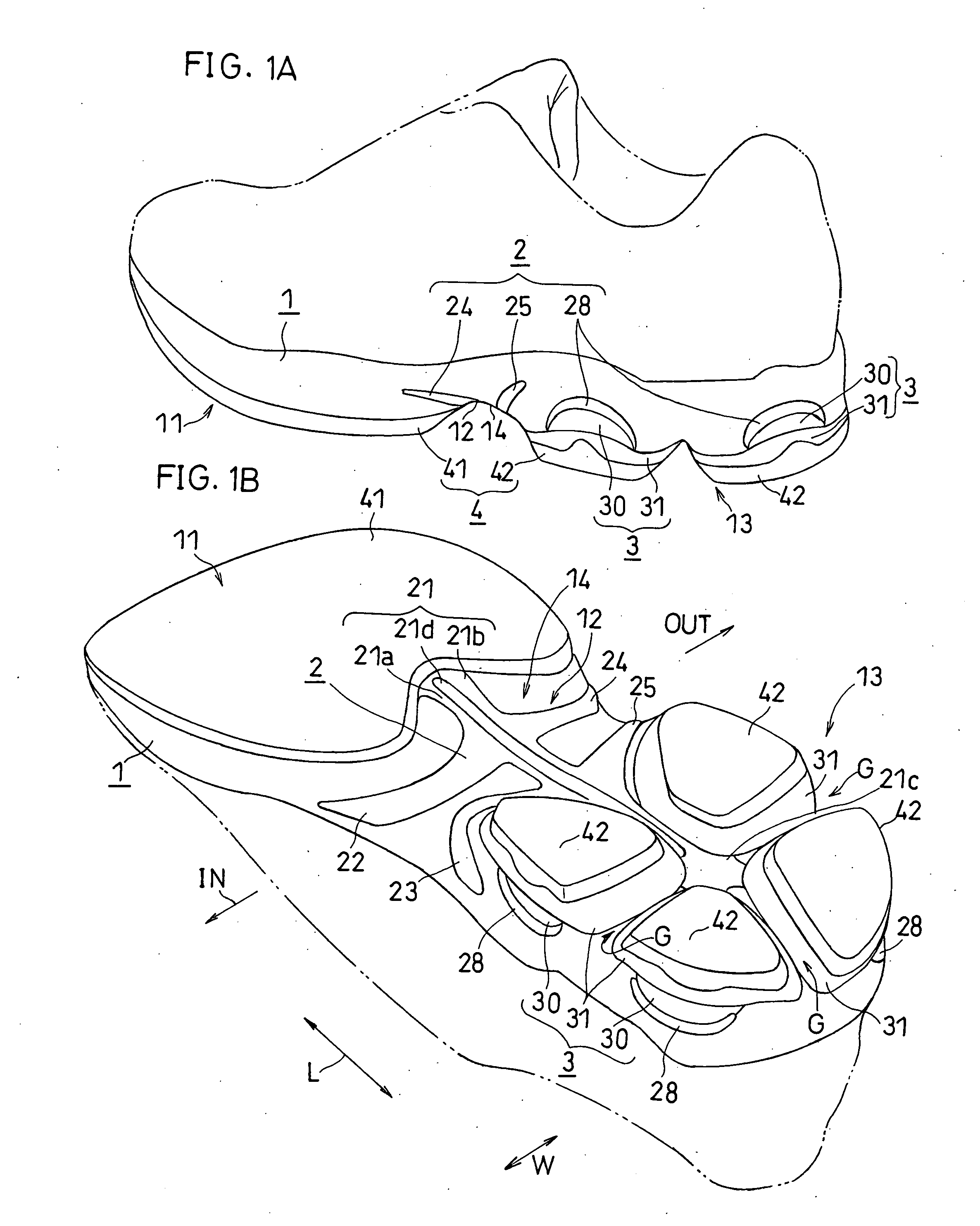
[0175]FIG. 1A to FIG. 7D each illustrates a first embodiment. In this and subsequent figures, “IN” and “OUT” denote the medial side and the lateral side of the foot, respectively. These figures show the structures while omitting design bumps / grooves. Such design bumps / grooves may be added as needed.
[0176]The following description is directed to a shoe sole for the left foot.
[0177]General Configuration:
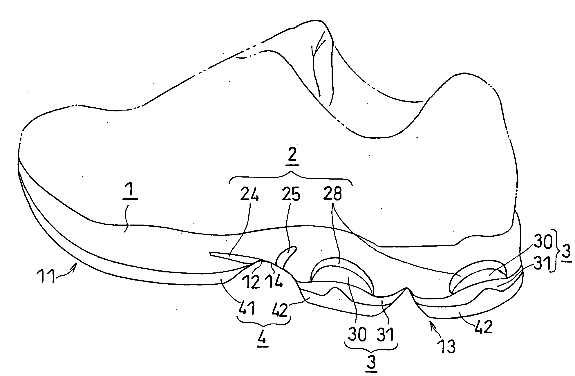
[0178]As shown in FIGS. 1A and 1B, a shoe sole of the present embodiment includes an upper mid sole 1, a reinforcing member 2, a lower mid sole 3 and an outer sole 4. In FIGS. 1A and 1B, a two-dot chain line represents the upper. The upper mid sole 1 and the lower mid sole 3 together form a mid sole. In a rear foot part 13, the lower mid sole 3 is divided into four portions.
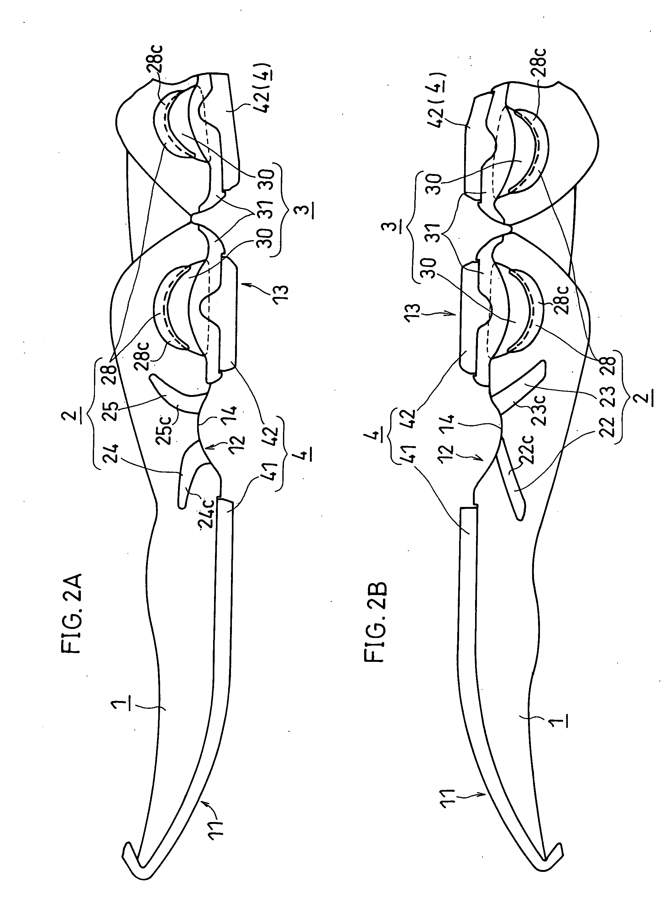
[0179]As shown in FIGS. 2A and 2B, the mid sole includes a fore foot part 11, a mid foot part 12 and the rear foot part 13.
[0180]The outer sole 4 is divided into a front outer sole 41 and a rear outer sole 42. The f...
second embodiment
[0248]A second embodiment will now be described with reference to FIG. 11A to FIG. 13B. In this and subsequent embodiments, like elements to those of the first embodiment are denoted by like reference numerals and will not be further described below.
[0249]As shown in FIGS. 11A and 11B, the compression deformation member 30 in the rear foot part is held between the upper mid sole 1 and the reinforcing member 2 in the present embodiment. The joined portion 27, to which the lower surface of the compression deformation member 30 is secured, is formed on the upper surface of the reinforcing member (the holding member) 2.
[0250]As shown in FIG. 12, in the present embodiment, there are a pair of compression deformation members 30, each being formed in a generally V-letter shape. The pair of compression deformation members 30, are arranged generally in symmetry. The joined portion 27 is also formed in a generally V-letter shape conforming to the shape of the compression deformation member 30...
third embodiment
[0252]Next, a third embodiment will be described with reference to FIGS. 15A and 15B.
[0253]As shown in FIGS. 15A and 15B, in the present embodiment, as opposed to the first embodiment, the rear foot blades 26a and 26b do not reach the side surface of the mid sole, whereby the edges of the rear foot blades 26a and 26b are not exposed on the side surface of the mid sole, and there is no first engagement portion.
[0254]On the side surface of the mid sole where the compression deformation member 30 is exposed, and in the vicinity thereof, the compression deformation member 30 is sandwiched between the upper and lower mid sole bodies 1 and 31. On the other hand, in areas where the rear foot blades 26a and 26b extend, the compression deformation member 30 is sandwiched and held between the holding member (reinforcing member) 2 and the lower mid sole body 31.
[0255]In the present embodiment, the outer sole 4 is rolled up along the side surface of the second engagement portion 32 of the lower...
PUM
 Abstract
Description
Claims
Application Information
 - R&D
- Intellectual Property
- Life Sciences
- Materials
- Tech Scout
- Unparalleled Data Quality
- Higher Quality Content
- 60% Fewer Hallucinations
Browse by: Latest US Patents, China's latest patents, Technical Efficacy Thesaurus, Application Domain, Technology Topic, Popular Technical Reports.
© 2025 PatSnap. All rights reserved.Legal|Privacy policy|Modern Slavery Act Transparency Statement|Sitemap|About US| Contact US: help@patsnap.com


