
Method for Regulating an Air-Fuel Mixture For An Internal-Combustion Engine

Inactive Publication Date: 2009-04-30
BAYERISCHE MOTOREN WERKE AG
View PDF3 Cites 22 Cited by
  • Summary
  • Abstract
  • Description
  • Claims
  • Application Information

AI Technical Summary

Benefits of technology

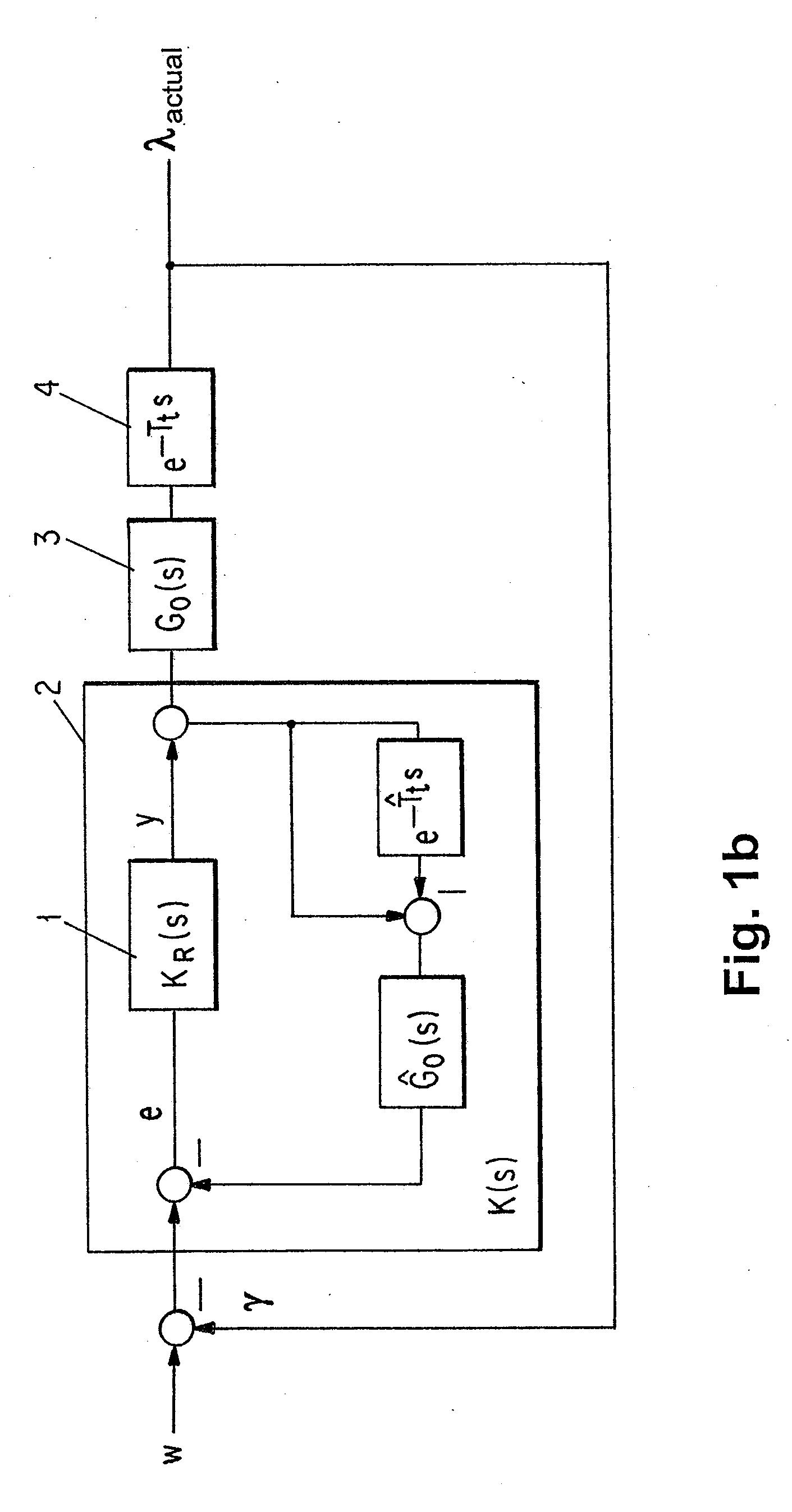
[0013]Preferably, at least one parameter of the Smith predictor, particularly the parameter concerning the transferred system parameter (this is preferably the system dead time) can be changed online, that is, during the operation of the control loop. This advantageous further development of the invention makes it possible to optimally coordinate the control with a change of the system parameters. The system dead time or another system parameter can then be newly determined during the operating time and can be transferred to the Smith predictor. The new determination and transfer can, for example, take place continuously, quasi-continuously, at regular intervals, or in an event-controlled manner. The lambda control according to such a further development of the invention is therefore suitable to adapt itself in a self-learning manner to changed system parameters.
[0014]At least one system parameter of the controlled system, particularly the system dead time, is preferably determined by an analysis of the variation in time of the actual lambda value as a result of a forced excitation fed into the control loop. The forced excitation can particularly be modulated upon the lambda setpoint.
[0015]As known from the state of the art, the forced excitation can be calculated out of the actual lambda signal again by way of a lambda model in order not to excite the control.
[0016]In particular, the system dead time can be determined in that the time

Problems solved by technology

For reaching certain target values and/or for observing legally prescribed limit values for exhaust emissions, very high technical expenditures are required.
The pilot control and other correction measures alone are not sufficient for optimally guiding the lambda value in the transient operation.
The concepts of the lambda control known from the state of the art—these are usually robust controllers (such as H∞ controllers) designed offline in the fre

Method used


Image

  • Method for Regulating an Air-Fuel Mixture For An Internal-Combustion Engine
  • Method for Regulating an Air-Fuel Mixture For An Internal-Combustion Engine
  • Method for Regulating an Air-Fuel Mixture For An Internal-Combustion Engine

Examples


Example

DETAILED DESCRIPTION OF THE DRAWINGS

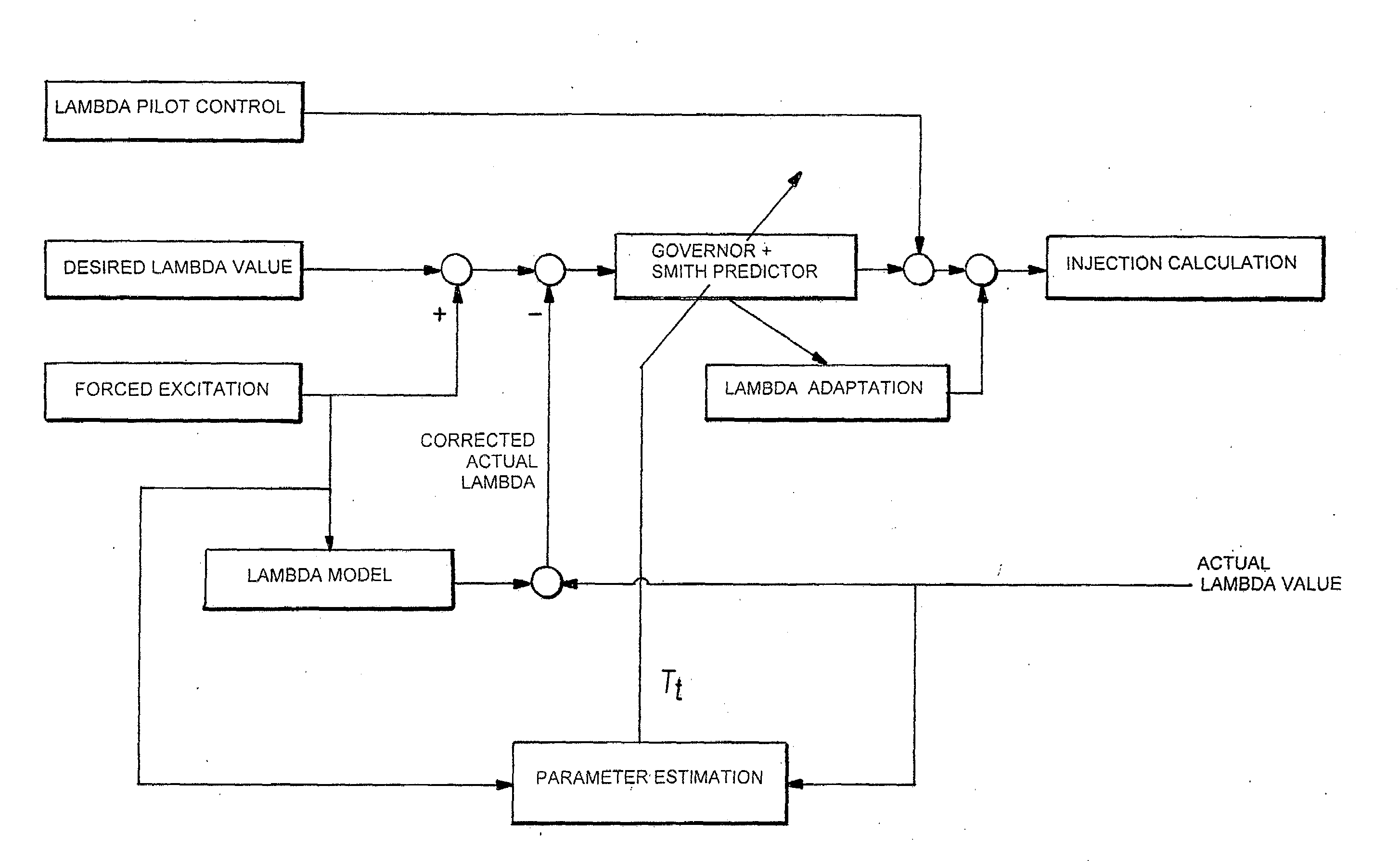
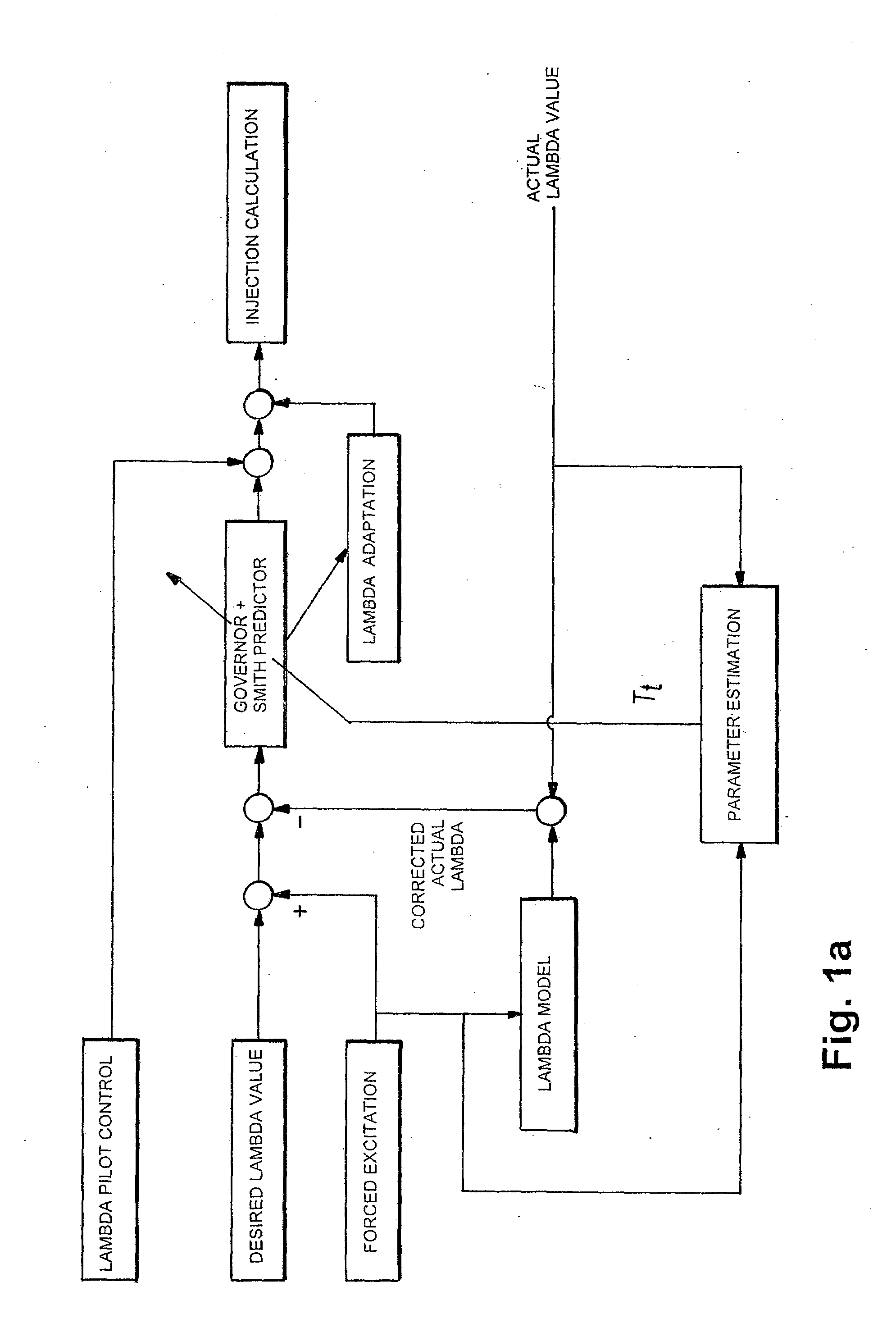
[0031]FIG. 1a illustrates a structural diagram of a method according to a preferred embodiment of the invention. The illustration in FIG. 1a contains the following signals and processing steps: A lambda setpoint is acted upon by a forced excitation and, minus a corrected actual lambda value, is fed into a controller with a Smith predictor. The forced excitation is also fed into a lambda model whose output is added to an uncorrected actual lambda value, which results in the corrected actual lambda value. In addition, the forced excitation and the uncorrected actual lambda value are fed into a parameter estimation. By use of the parameter estimation, a dead time Tt is determined and is transferred to the controller with the Smith predictor. The controller output is acted upon by a lambda pilot control. The resulting signal is additionally acted upon by the output signal of a lambda adaptation and is transferred to an injection calculation. The lambd...


PUM


Abstract

A method of regulating the actual lambda value for an internal-combustion engine of a motor vehicle in a closed control loop is provided. A lambda setpoint is transferred to a controller for influencing an injection calculation for the internal-combustion engine, and an actual lambda value, which occurs at the output of a controlled system as a function of the injection calculation, is returned to the controller. At least one system parameter of the controlled system is determined, and the determined system parameter is transferred to a Smith predictor added to the controller for compensating the influence of the system dead time on the control loop characteristics.

Description

CROSS-REFERENCE TO RELATED APPLICATION[0001]This application is a continuation of PCT International Application No. PCT / EP2006 / 001816, filed on Feb. 28, 2006, the entire disclosure of which is expressly incorporated by reference herein.BACKGROUND AND SUMMARY OF THE INVENTION[0002]The invention relates to a method of regulating the air-fuel mixture in the case of an internal-combustion engine of a motor vehicle in a closed control loop, where a lambda setpoint is transferred to a controller for influencing an injection calculation for the internal-combustion engine. The actual lambda value, which occurs at the output of a controlled system as a function of the injection calculation, is returned to the controller.[0003]The reduction of exhaust emissions represents a central theme in the development of modern motor vehicles. For reaching certain target values and / or for observing legally prescribed limit values for exhaust emissions, very high technical expenditures are required.[0004]...

Claims


Application Information

Patent Timeline
IPC IPC(8): F02D41/30
CPCF02D41/1401F02D2041/1433F02D2041/1431F02D41/1475
Inventor PERSCHL, FRANZDUMELE, EDITH HEIDIBUSS, MARTIN
Owner BAYERISCHE MOTOREN WERKE AG
Learn More