
Vehicle drive apparatus

a technology of drive apparatus and vehicle, which is applied in the direction of electric propulsion mounting, braking system, transportation and packaging, etc., can solve the problems of insufficient performance and deterioration of achieve the effect of improving the drivability of the vehicl

Active Publication Date: 2009-04-30
TOYOTA JIDOSHA KK
View PDF6 Cites 32 Cited by
  • Summary
  • Abstract
  • Description
  • Claims
  • Application Information

AI Technical Summary

Benefits of technology

[0006]In view of the above, the invention has been made to provide a vehicle drive apparatus that achieves the performance desired by the driver and thereby improves the drivability of the vehicle.
[0008]As mentioned above, this vehicle drive apparatus determines the drive forces that for the left and right drive wheels based on the total drive force for the drive wheels, the drive reaction forces at the drive wheels, and at least two of the target moment required in the yaw direction of the vehicle, the target moment required in the roll direction of the vehicle, and the target moment required in the pitch direction of the vehicle. Then, the vehicle drive apparatus controls the drive forces at the respective drive wheels so as to achieve at least two of the target yaw moment, the target roll moment, and the target pitch moment. Thus, the vehicle drive apparatus according to the first aspect of the invention achieves the performance desired by the driver and thereby improves the drivability of the vehicle.
[0020]As such, the vehicle drive apparatus according to the invention achieves the performance desired by the driver and thereby improves the drivability of the vehicle.

Problems solved by technology

However, since the control performed by the drive apparatus described in this publication only suppresses the rolling of the vehicle, the yaw moment of the vehicle may become less than the level needed for the vehicle to turn appropriately or may exceed that level, and this will deteriorate the drivability of the vehicle.
That is, in this case, the performance desired by the driver can not be achieved sufficiently.

Method used


Image

  • Vehicle drive apparatus
  • Vehicle drive apparatus
  • Vehicle drive apparatus

Examples


Embodiment Construction

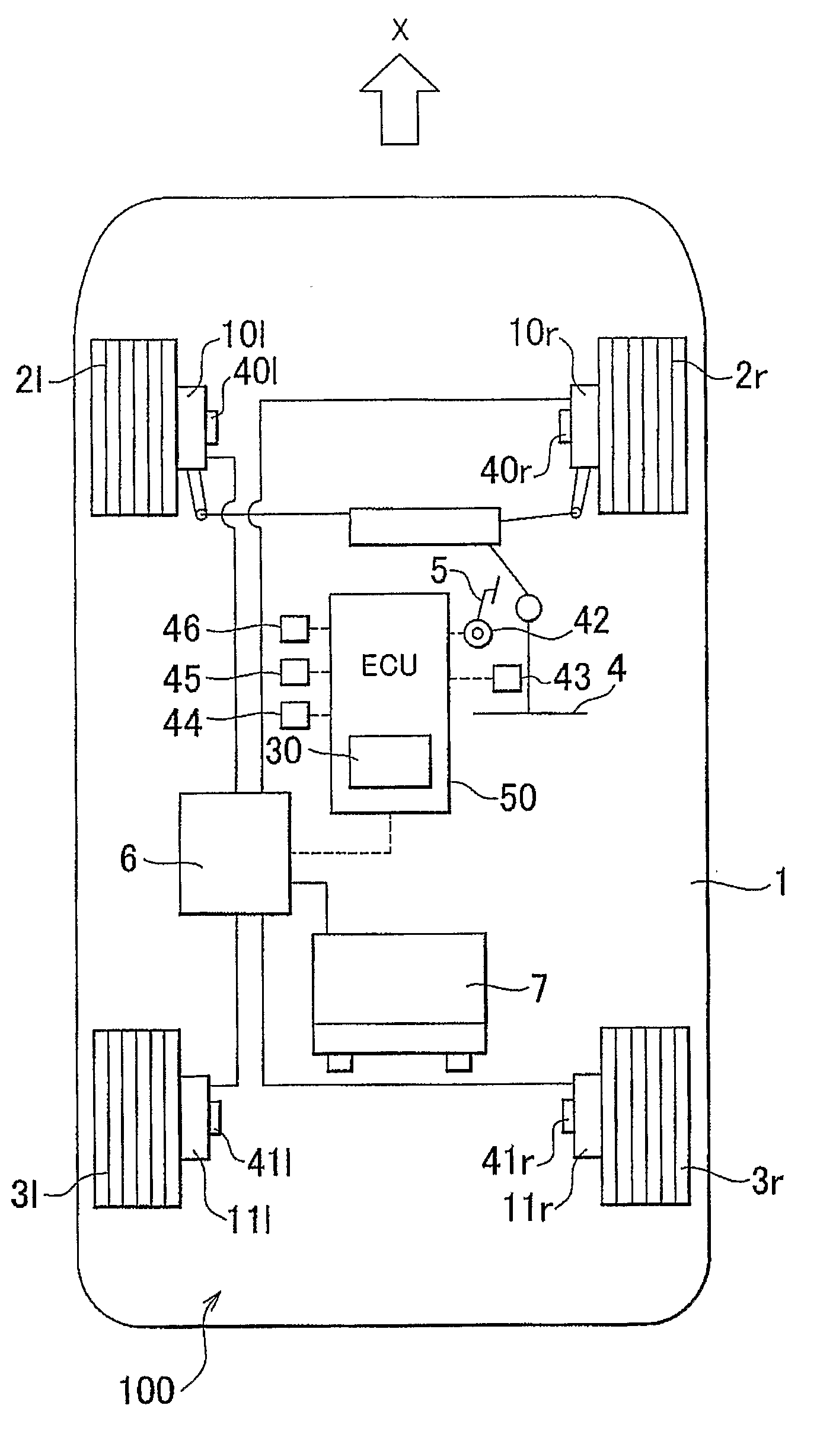
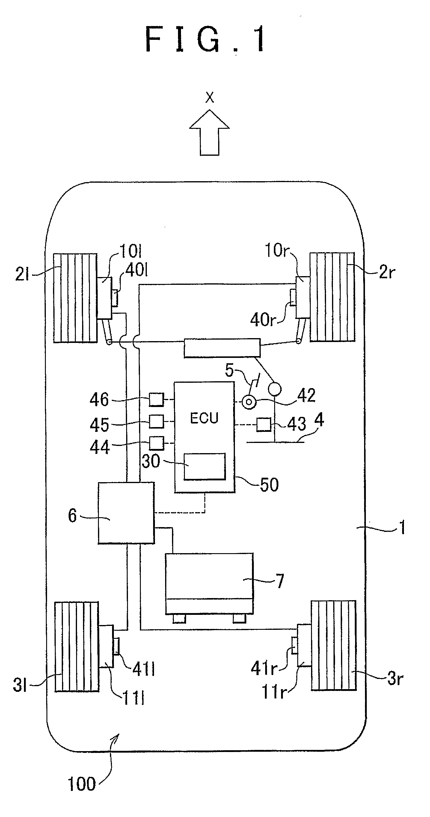
[0034]In the following description and the accompanying drawings, the present invention will be described in more detail with reference to exemplary embodiments. In the following exemplary embodiments, the invention is mainly applied to electric motor vehicles. However, applications of the invention are not limited to electric motor vehicles, but may be any vehicles in which different drive forces can be provided at at least a pair of left and right drive wheels, respectively. The drive force for the right drive wheel and the drive force for the left drive wheel may by controlled by controlling each drive force independently or by controlling the distribution ratio of drive force between the left and right drive wheels.

[0035]First, a vehicle drive apparatus according to the first exemplary embodiment of the invention will be described. The vehicle drive apparatus is characterized in the following feature. First, the drive forces for the right and left drive wheels are determined bas...


PUM


Abstract

A vehicle drive apparatus independently controls drive forces for a front-right drive wheel, a front-left drive wheel, a rear-right drive wheel, and a rear-left drive wheel using a front-right electric motor, a front-left electric motor, a rear-right electric motor, and a rear-left electric motor, respectively. The drive forces for the drive wheels of a vehicle incorporating the vehicle drive apparatus are determined based on the target moments in the yaw and roll directions of the vehicle, the total drive for the drive wheels, and the drive reaction forces at the drive wheels. Thus, the performance desired by the driver can be achieved, and the drivability therefore improves accordingly.

Description

BACKGROUND OF THE INVENTION[0001]1. Field of the Invention[0002]The invention relates to a vehicle drive apparatus that can provide different drive forces at at least a pair of left and right wheels.[0003]2. Description of the Related Art[0004]When a vehicle, such as a passenger vehicle and a truck, is turning at a curve, the vehicle rolls due to inertial force acting toward the outer side of the curve. Japanese Patent Application Publication JP-A-2005-306152 describes a drive apparatus that independently drives four wheels of a vehicle and suppresses the rolling of the vehicle by controlling the drive force for each drive wheel.[0005]However, since the control performed by the drive apparatus described in this publication only suppresses the rolling of the vehicle, the yaw moment of the vehicle may become less than the level needed for the vehicle to turn appropriately or may exceed that level, and this will deteriorate the drivability of the vehicle. That is, in this case, the per...

Claims


Application Information

Patent Timeline
Patent Type & Authority Applications(United States)
IPC IPC(8): B60K7/00B60W30/045B60L15/20
CPCB60G7/008Y02T10/7258B60G21/051B60G2200/142B60G2200/21B60G2200/422B60G2204/129B60G2204/148B60G2204/30B60G2206/20B60G2300/50B60G2800/952B60K17/356B60K23/0808B60W30/04B60W30/045B60W2720/14B60W2720/30B60G17/0195B60W2540/18Y02T10/72B60W30/188B60W40/10
Inventor MAEDA, YOSHINORIHOSOKAWA, AKIHIROSUZUKI, YOUSUKETSUCHIDA, MICHITAKAOKUMURA, KAZUYAOSHIUMI, TADAHIROYOSHIZUE, KENSUKESUGIYAMA, KOJI
Owner TOYOTA JIDOSHA KK
Learn More