
Back-up electric power generator for electronic components attached to automatic firearms

a technology of electronic components and electric power generators, which is applied in the direction of machines/engines, transportation and packaging, lighting and heating apparatus, etc., can solve the problems of iron sights, sight or sighting equipment that cannot operate, rendering it useless

Inactive Publication Date: 2009-04-30
BALLISTO
View PDF48 Cites 71 Cited by
  • Summary
  • Abstract
  • Description
  • Claims
  • Application Information

AI Technical Summary

Benefits of technology

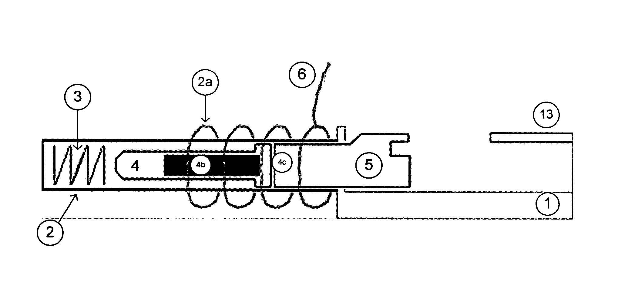
"The present invention is a firearm improvement that acts as a dynamo or electric generator. It includes several components that either replace or are added to the firearm. The device generates electric energy that is stored in a capacitor, battery, or other component for later use as a back-up power supply for electronic components attached to or incorporated into the firearm. The invention is a device for generating and storing electric power and attached to, or made a part of, a weapon. It includes a magnet, conductor assembly, and electric power storage unit. The invention allows for the efficient use of electric energy from a firearm and provides a reliable power source for electronic components."

Problems solved by technology

Iron sights, unless they are augmented by certain equipment, such as tritium inserts, are difficult to use in low light levels or at night; consequently, night-vision equipment or infrared laser sights must be attached to the firearm so that the shooter may use the firearm in such conditions.
The sight or sighting equipment will fail to operate without this power source, rendering it useless and either requiring the shooter to return to using the firearm's iron sights or to replace the power source of the sight.
If the shooter is a combat soldier relying on a piece of electronic sighting equipment, failure to carry a source of back-up power could leave the soldier stranded in the field with a firearm which he cannot properly aim.
This situation could lead to tragic results for the soldier or his unit.

Method used


Image

  • Back-up electric power generator for electronic components attached to automatic firearms
  • Back-up electric power generator for electronic components attached to automatic firearms
  • Back-up electric power generator for electronic components attached to automatic firearms

Examples


Embodiment Construction

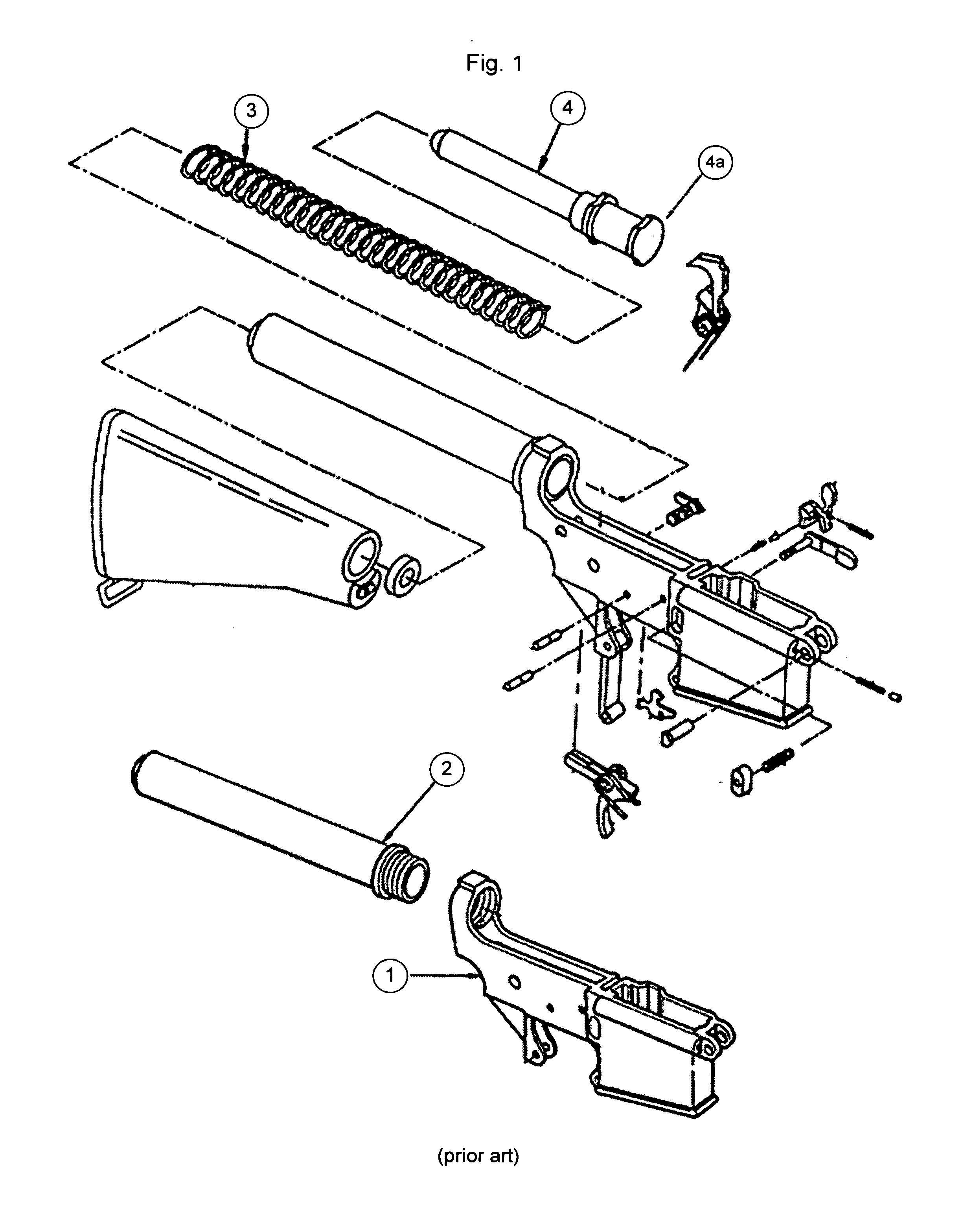
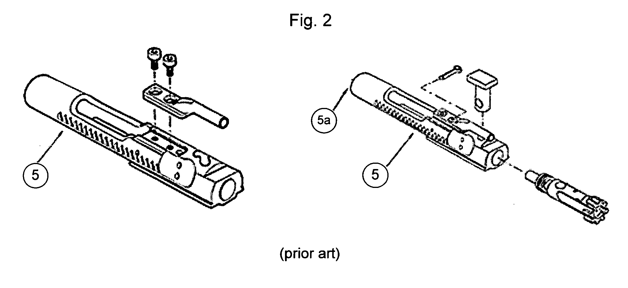
[0028]In one embodiment, the invention is an assembly comprising a group of mechanical components which are either added to an automatic firearm or which are derivatives of existing parts of an automatic firearm and then substituted for the original parts of an automatic firearm. A person skilled in the arts of manufacturing and / or designing mechanical devices may make the invention from modifications to existing rifle parts, by manufacturing rifle parts with the described modifications to certain standards, and by the addition of other pre-manufactured parts to complete the invention.

[0029]Although this application describes the necessary modifications which must be made to an AR-15 rifle to implement the invention, those skilled in the arts of mechanical component manufacture and / or design will be able to make appropriate modifications to other automatic firearms in order to implement the invention on such firearms. As the AR-15 design is widely used by various military units of t...


PUM


Abstract

A firearm improvement taking the form of a mechanical dynamo installed in an automatic firearm. Several components either replace certain parts of the firearm or are added to the firearm. In conjunction with the operation of the firearm, the components generate electric energy which is then stored in a capacitor, battery, or other element for the storage of electric energy, or supply power to a battery recharging unit attached to the firearm. The electric energy contained in the storage component, or used to recharge the batteries placed in the recharging unit, may be used at a later time as a back-up power supply for electronic components attached to or incorporated into the firearm, such as red-dot or reflex sights, laser sighting equipment, or night vision equipment.

Description

CROSS REFERENCE TO RELATED APPLICATIONS[0001]This nonprovisional patent application claims the benefit of the filing date of provisional application 60 / 707,270, filed Aug. 11, 2005, which is herein incorporated by reference.BACKGROUND OF THE INVENTION[0002]A review of certain aspects of the background of the invention provides insight into how the invention operates and the benefits provided by the invention. A discussion of the use and limitations of electronic sighting equipment for firearms is presented, followed by a discussion of the operation of semiautomatic firearms and then by an overview of the theory and application of electromagnetic induction.Firearm Sights[0003]Operators of firearms traditionally used “iron sights” to designate their targets. These iron sights generally consist of a blade or post attached at the muzzle end of the firearm's barrel and a peephole or notch sight at the breech end of the firearm's barrel. Iron sights have certain disadvantages and are ofte...

Claims


Application Information

Patent Timeline
Patent Type & Authority Applications(United States)
IPC IPC(8): H02K35/02F41A35/00
CPCF21L13/00H02K35/02H02K7/1876F21L13/08
Inventor RACHO, JEFFREY
Owner BALLISTO
Learn More