High strength fastener system

a fastener and high-heavy technology, applied in the direction of wrenches, screwdrivers, fastening means, etc., can solve the problems of torque exceeding the strength limits of the drivers used, and achieve the effects of increasing the core diameter, increasing the seat torque capability, and increasing the driver strength

Active Publication Date: 2009-04-23
PHILLIPS SCREW
View PDF7 Cites 16 Cited by
  • Summary
  • Abstract
  • Description
  • Claims
  • Application Information

AI Technical Summary

Benefits of technology

[0008]A fastener system is constructed having driver/fastener interface surfaces configured in the general shape of a segment of a spiral on both of the installation and removal surfaces. The recess and driver cross sectional shapes are constructed with an increased core diameter over the prior art spiral fastener system. This is accompanied by a shortening of the radial extension of the wing of both recess and driver cross sections beyond the core diameter. The wing cross section of the driver/recess is further modified by moving the installation and removal surfaces in a parallel manner to form a truncated wing shape with a blunt tip. The blunt tip is constructed to conform to a circle, concentric with the core, with a diameter larger than the core diameter. The drive surfaces are constructe

Problems solved by technology

Such torques may exceed the strength limits of the drivers used to seat the fastener.
The problem to which this application is directed, therefore, is to construct a drive fastener interface that increases the strength of the driver without significantly effecting the load distribution characteristics of the spiral interface surfaces.

Method used


Image

  • High strength fastener system
  • High strength fastener system
  • High strength fastener system

Examples


Embodiment Construction

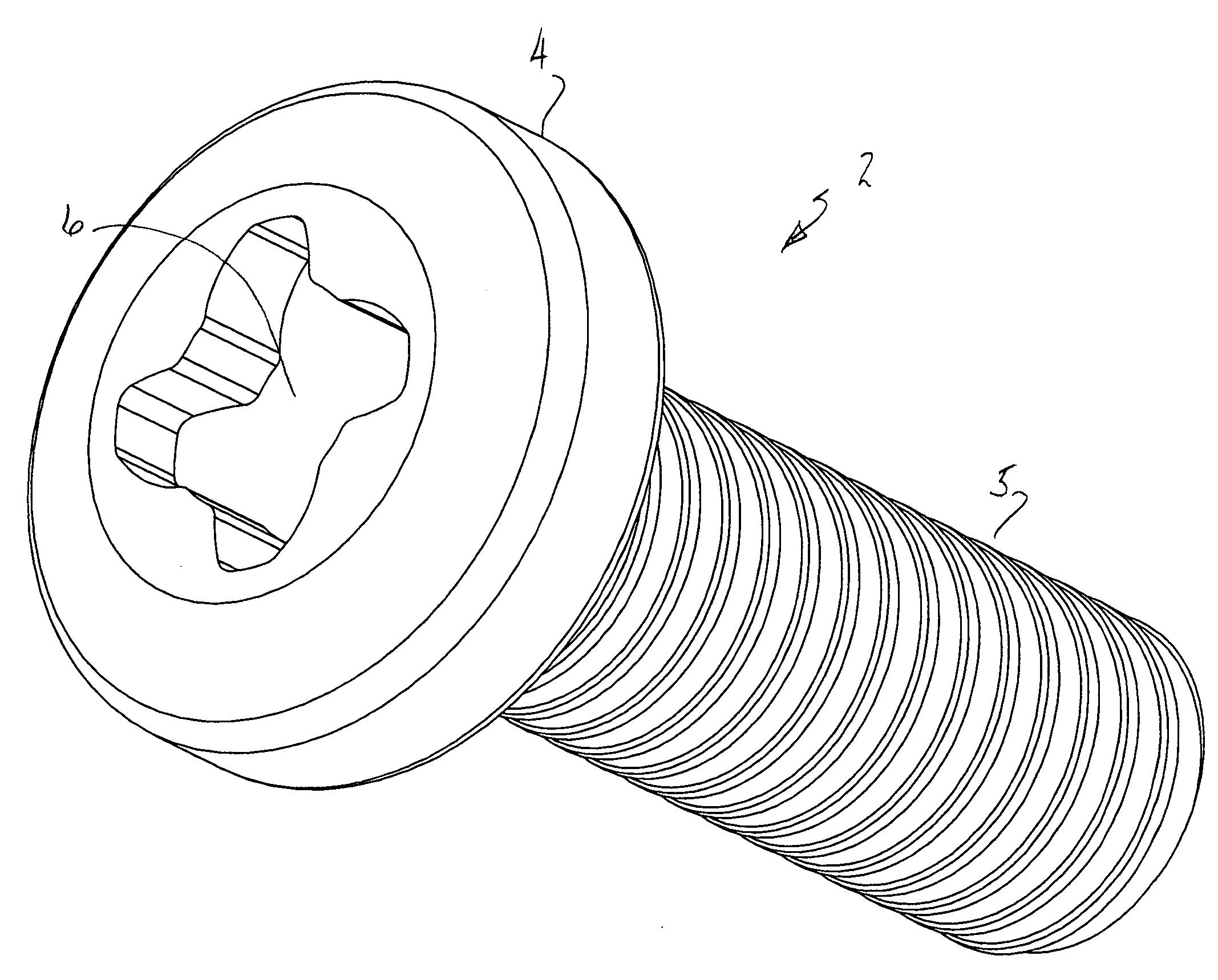
[0017]FIGS. 3 and 4 of this application illustrate, as an example, a fastener and driver bit of a fastener system having features of an embodiment of this application. Although the embodiments disclosed will be described with reference to the drawings, it should be understood that they may take many alternate forms.

[0018]A fastener system 1, according to the subject of this application, is shown in FIGS. 3 and 4 and consists of fastener 2 and driver bit 3. Fastener 2 is constructed having a head 4 and a threaded shank 5. A spirally configured recess 6 is formed in head 4. Driver bit 3 is constructed having spirally configured drive surfaces that mate with the corresponding surfaces of fastener recess 6. As shown in the example of FIG. 4, driver bit 3 utilizes a generally cruciform shape having wings 7a,b,c, and d. Similarly to prior art spirally configured fasteners, the overall shapes and number of wings may be varied from the example illustrated. Each of the wings have a substanti...


PUM

PropertyMeasurementUnit
Ratioaaaaaaaaaa
Shapeaaaaaaaaaa
Radiusaaaaaaaaaa

Abstract

A fastener system is constructed wherein the installation and removal drive surfaces intersect an enlarged core diameter in a transitional surface that extends between the installation and removal surfaces of adjacent wings. The transitional surface has a concave form that conforms to the core diameter. The projections of the driver in the system are formed in a blunt shape.

Description

RELATED APPLICATIONS [0001]This application claims priority from Provisional Application for Patent No. 60 / 999,874, filed Oct. 22, 2007.BACKGROUND[0002]1. Field[0003]The disclosed embodiments generally relate to fastener systems including fastener, driver, method of manufacture and related tooling. In particular to fasteners having spiral drive and removal surfaces that enable high seating torques to be applied.[0004]2. Brief Description of Related Developments[0005]Fasteners having driver engageable surfaces that are, at least in part, defined by spiral segments have been used with good results. Fastener systems of this type are described in U.S. Pat. Nos. 5,957,645, 6,234,914, and 6,367,358 issued to Stacy and commonly owned with this application. The disclosures of these patents are incorporated herein by reference. The drive surfaces of the Stacy fastener system are constructed to maximize torque transmission, during installation and removal, while spreading the driving load ove...

Claims


Application Information

Patent Timeline
IPC IPC(8): F16B23/00B25B23/02B23P17/00
CPCB25B15/005Y10T29/49F16B23/0023
Inventor DILLING, GARY
Owner PHILLIPS SCREW
Why Eureka
Try Eureka