
Data transfer device for ring protocol high speed switching and method for the same

a data transfer device and high-speed switching technology, applied in data switching networks, digital transmission, electrical devices, etc., can solve the problems of difficult to maintain high-speed switching processes, control frames will no longer be received by the port on the other side, and the flow is interrupted, etc., to achieve flexible, increase the number of rings, and facilitate the effect of high-speed switching

Inactive Publication Date: 2009-04-23
ALAXALA NETWORKS
View PDF7 Cites 7 Cited by
  • Summary
  • Abstract
  • Description
  • Claims
  • Application Information

AI Technical Summary

Benefits of technology

The present invention provides a technology for deployment in a ring network that can flexibly adapt to higher switching process speeds and increased numbers of rings. It includes a data transfer device with a controller portion that can switch ring management resources and balance network load. The device has multiple frame processing portions and a destination determining portion for efficient data transfer. The invention also provides a data transfer method for controlling ring management resources and connection lines. Overall, the invention improves network efficiency and flexibility.

Problems solved by technology

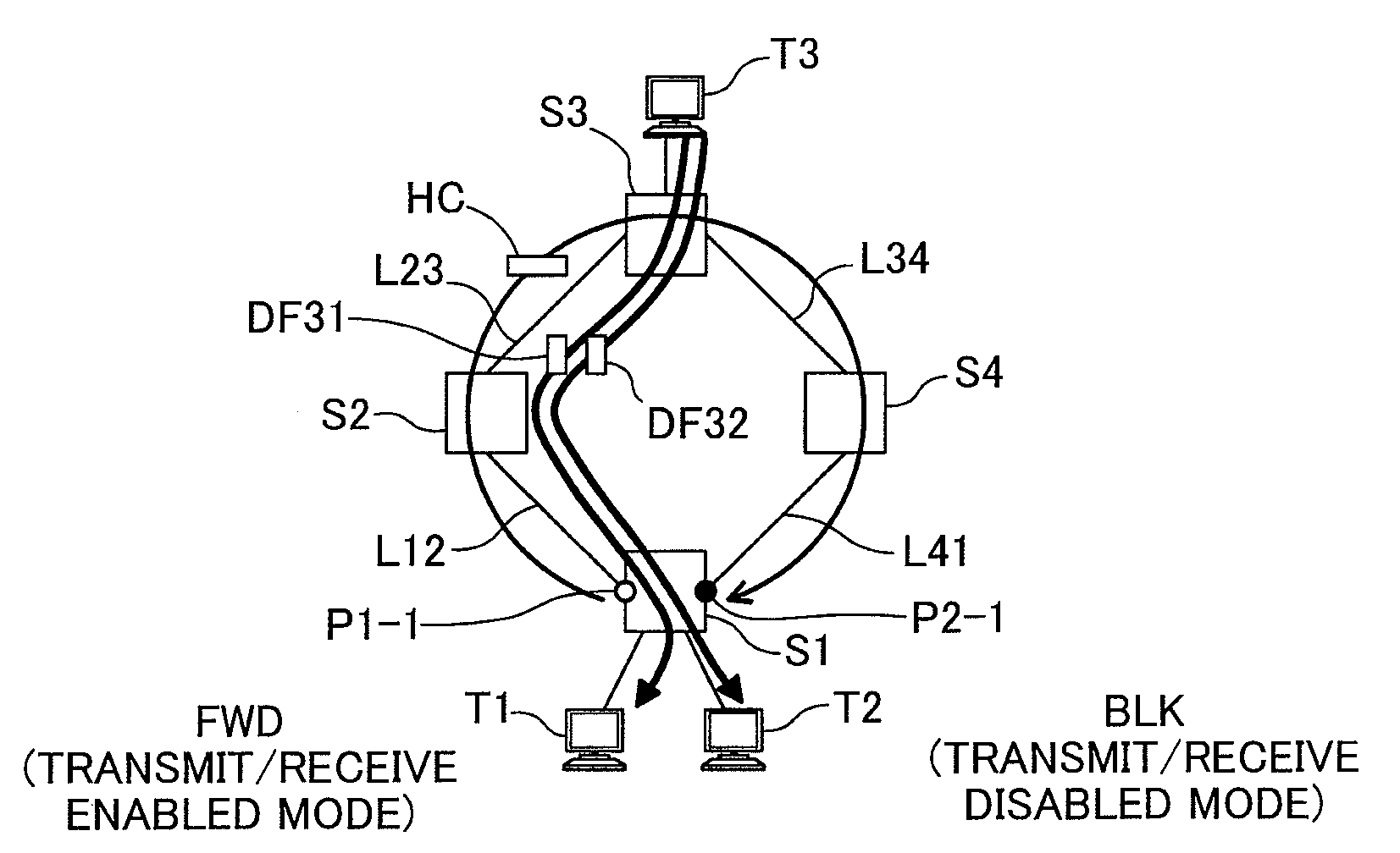
In a ring network configured with ring topology, failure in of even one data transfer device or transmission path will result in interrupted flow of data, so in the event of a failure on the network it is important to detect the failure and quickly switch the pathway.
During the period that control frames are received by the port on the opposite side the ring network will be considered as operating normally; however, if a failure occurs on the network, control frames will no longer be received by the port on the opposite side, and it will therefore be possible to detect that failure has occurred.
It has proven difficult to maintain high-speed switching processes and to ensure scalability accommodating a larger numbers of rings in the network, while maintaining reliability.

Method used


Image

  • Data transfer device for ring protocol high speed switching and method for the same
  • Data transfer device for ring protocol high speed switching and method for the same
  • Data transfer device for ring protocol high speed switching and method for the same

Examples


Embodiment Construction

[0054]A. Network Transfer System in an Embodiment of the Present Invention:

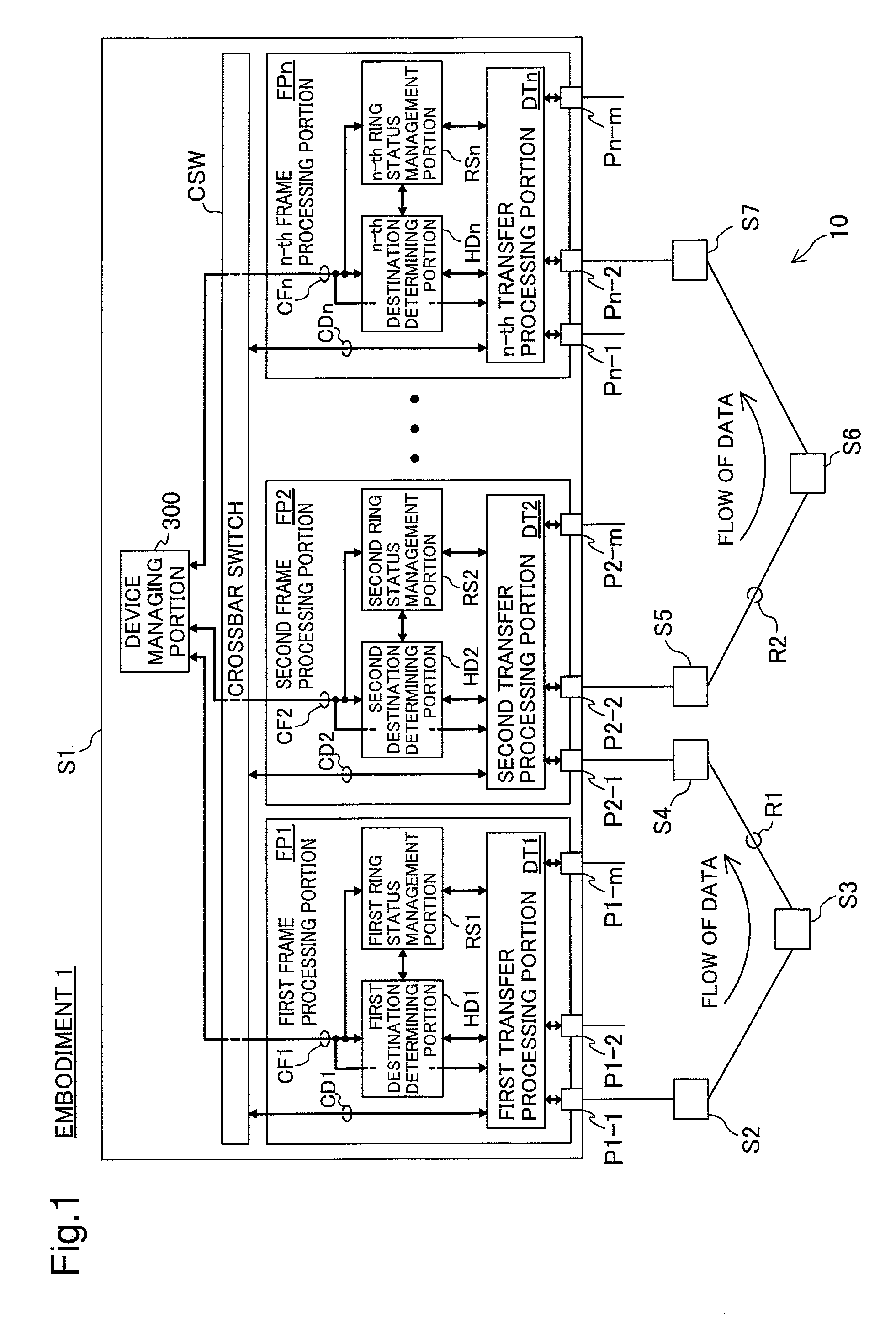
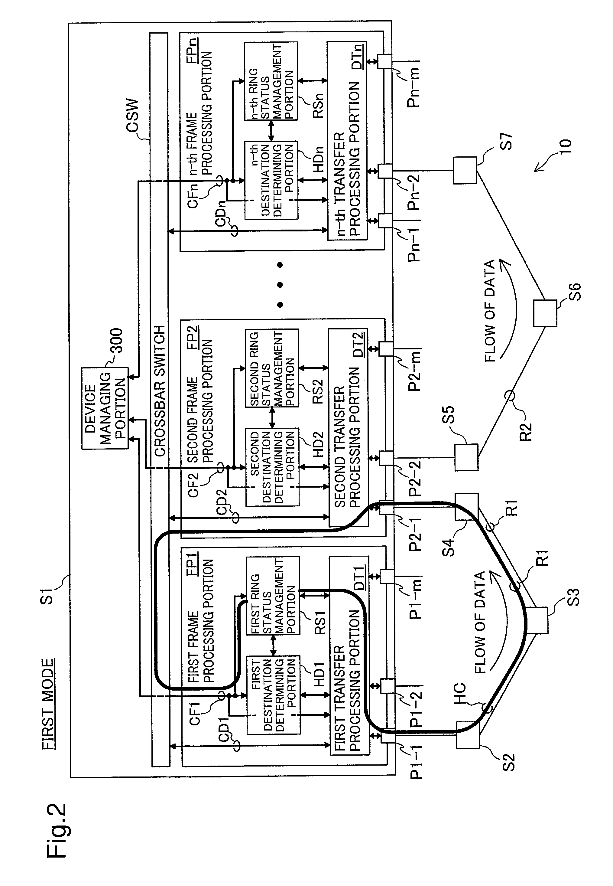
[0055]FIG. 1 is a block diagram depicting in overview a ring network system in an embodiment of the present invention. The ring network system of the present embodiment includes two rings R1, R2. The ring R1 and the ring R2 respectively include four switches S1 through S4, and four switches S1 and S5 through S7. The switch S1 has a number n of first through n-th frame processing portions FP1 through FPn; a crossbar switch CSW interconnecting these frame processing portions FP1 through FPn; and a device managing portion 300 for managing these components.

[0056]The first frame processing portion FP1 has a first destination determining portion HD1; a first ring status management portion RS1; a first transfer processing portion DT1; and a number m of input / output ports P1-1 through Pn-m. In the embodiment, the other frame processing portions FP2 through FPn each have a configuration identical to the first frame pr...


PUM


Abstract

The present invention provides a data transfer device. This data transfer device comprises a number n (where n is an integer equal to 2 or greater) of transfer resources functioning as nodes of ring networks and connection lines connecting a number m (where m is an integer equal to 2 or greater) of ring networks and the number n of transfer resources. The connection lines are configured to be capable to connect at least some of the m ring networks and at least some of the n transfer resources. A controller controls transfer resource specified among at least some of the transfer resources to manage at least some of m number of ring networks.

Description

CROSS REFERENCE TO RELATED APPLICATIONS[0001]This application relates to and claims priority from Japanese Patent Applications No. 2007-273770, filed on Oct. 22, 2007, the entire disclosure of which is incorporated by reference.BACKGROUND[0002]1. Technical Field[0003]The present invention relates to a technology for data transfer in a ring network.[0004]2. Background of the Related Art[0005]Ring networks enjoy widespread use due to their high reliability and smaller requirements for transmission path and interfaces. In a ring network configured with ring topology, failure in of even one data transfer device or transmission path will result in interrupted flow of data, so in the event of a failure on the network it is important to detect the failure and quickly switch the pathway.[0006]One method for detecting failure of a data transfer device or transmission path making up a ring network involves having one of the data transfer devices periodically transmit control frames to the rin...

Claims


Application Information

Patent Timeline
Patent Type & Authority Applications(United States)
IPC IPC(8): H04L12/56H04L12/437
CPCH04L12/437H04L12/4637H04L12/4625
Inventor AKAHANE, SHINICHIKODAMA, YASUHIROKOHNO, TOMOHIKONAGATA, TETSUYA
Owner ALAXALA NETWORKS
Learn More