
Systems and methods for detecting electric discharge

a technology of electric discharge and detection system, applied in the direction of optical radiation measurement, x/gamma/cosmic radiation measurement, instruments, etc., can solve the problems of arcing or shortening, brittle insulation, and increased arcs,

Inactive Publication Date: 2009-04-23
SENSORTRAN
View PDF5 Cites 15 Cited by
  • Summary
  • Abstract
  • Description
  • Claims
  • Application Information

AI Technical Summary

Benefits of technology

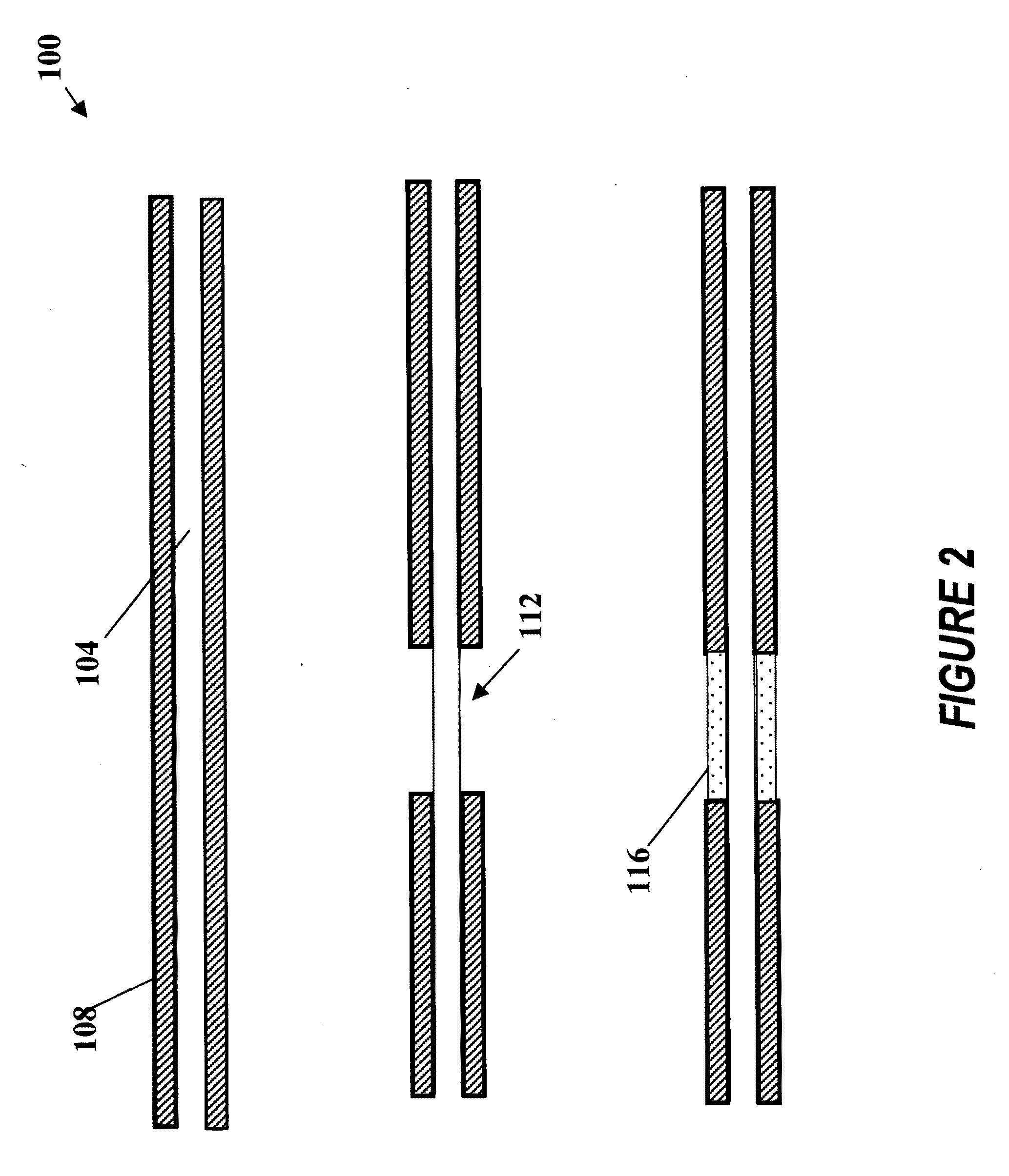
[0013]One aspect of the invention is a distributed sensing system for detecting partial electric discharge along the length of an extended object or objects on which a single line of silica core optical sensing fiber is deployed in close proximity comprising: a optical sensing fiber comprising: a silica core; a cladding surrounding the core; wherein a luminescent material is integrated into the cladding surrounding the core; and wherein the luminescent material is selected to interact with the photons of any electric discharge so that the photons are converted to near UV to visible light when exposed to electric discharge of the extended object or objects; and w...

Problems solved by technology

As electrical wires age, insulation may become brittle and crack leading to arcing or shorts.
Small arcs can carbonize the insulation, leading to bigger arcs and the potential for fire.
Therefore, intermittent partial discharge or arcing that can occur in flight may not be reproducible during ground maintenance.
But these devices provide limited coverage or require direct electrical connection, which can be inconvenient or even unsafe in some applications.
Such fibers have a limited transmission distance and poorer resistance to environmental conditions than optical fibers of a silica (glass) core.
Thus the plastic core fibers of these prior art references are significantly limited to very short sensor systems (around 10 m range) in favorable environments.

Method used


Image

  • Systems and methods for detecting electric discharge
  • Systems and methods for detecting electric discharge
  • Systems and methods for detecting electric discharge

Examples


Embodiment Construction

[0026]Preferred embodiments and their advantages are best understood by reference to FIGS. 1 through 5, wherein like numbers are used to indicate like and corresponding parts.

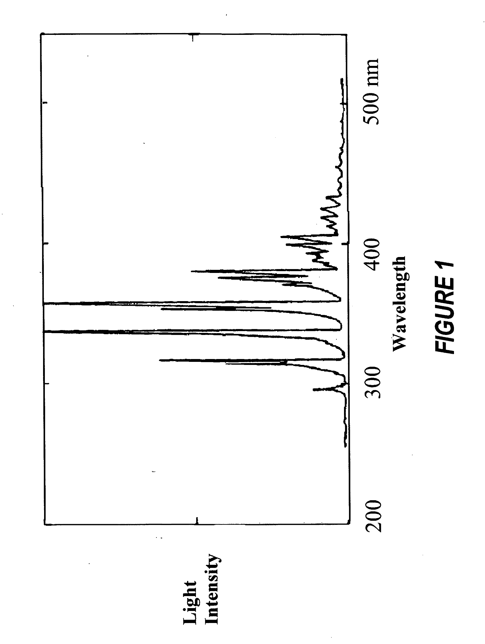
[0027]The present disclosure provides systems and methods for safe and continuous monitoring of wiring at low pressures by determining both the magnitude and location of wiring discharge. In particular, the present disclosure provides systems and methods for converting the emitted photons into near UV and visible light and detecting the light using fiber optics in a simplified scheme.

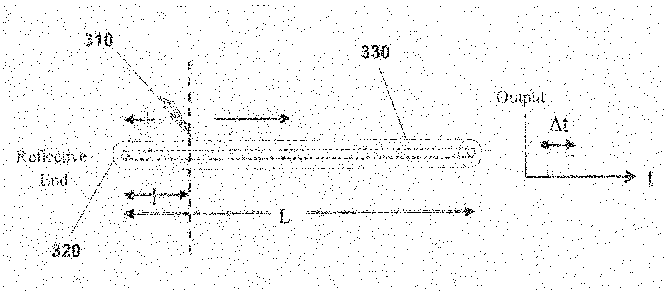
[0028]In one embodiment, photons generated by the intermittent discharges may be converted to near UV and visible light or other longer wavelength using a suitable fluorophore layer. The photons may interact with the fluorophore layer and subsequent scattered emission from the interaction may be detected and analyzed to characterize the discharges.

[0029]These photons can be converted to near UV and visible light (or longer waveleng...


PUM


Abstract

A distributed sensing system for detecting partial electric discharge along the length of an extended object or objects. An optical fiber having a cladding integrated with luminescent material and a silica core of less than 500 micro-meters in diameter with a first reflective end deployed in proximity to test objects. A photo detector is positioned at the second end of the optical sensing fiber and receives and measures both a direct emission light from an electric partial discharge event and the reflected emission light from the reflection end of the optical sensing fiber. The measured signals and their arrival times are used to determine the location and magnitude of a partial electrical discharge.

Description

CROSS REFERENCE TO RELATED APPLICATIONS[0001]This application claims the benefit of U.S. Provisional Ser. No. 60 / 981,765, filed Oct. 22, 2007 by the present inventors.BACKGROUND[0002]The present disclosure relates to electric partial discharge detection, and more particularly, to a system and method for detection and measuring electric partial discharge using an optical fiber.[0003]As electrical wires age, insulation may become brittle and crack leading to arcing or shorts. Small arcs can carbonize the insulation, leading to bigger arcs and the potential for fire. Control of electrical discharge is necessary to avoid degrading the insulation in electrical wires in air or in insulating oil. The need for reliable monitoring is increased when the cable is used in high altitude where ambient pressures may be well below one atmosphere such at flight altitudes. The inception level for discharges is reduced as pressure decreases. Therefore, intermittent partial discharge or arcing that can...

Claims


Application Information

Patent Timeline
IPC IPC(8): H01H9/50G01T1/20
CPCG01D5/30G01J1/58G01R31/1218G01D5/268G02B6/02052H02H1/0023G01R31/1272
Inventor LEE, CHUNGKALAR, KENT
Owner SENSORTRAN
Learn More