
Systems, Methods and Circuits for Determining Potential Battery Failure Based on a Rate of Change of Internal Impedance

a technology of internal impedance and system, applied in the field of battery monitoring, can solve problems such as catastrophic battery failure, irreversible and immediate battery failure, and reducing useful battery li

Active Publication Date: 2009-04-16
TEXAS INSTR INC
View PDF5 Cites 55 Cited by
  • Summary
  • Abstract
  • Description
  • Claims
  • Application Information

AI Technical Summary

Benefits of technology

[0001]The present invention is related to battery monitoring, and more...

Problems solved by technology

Indeed, most battery failure mechanisms operate to gradually decrease useful battery life and do not cause a safety hazard.
At times one or more mechanisms may come into play that result in the catastrophic battery failure.
Catastrophic battery failure may be benign resulting in, for example, an irreversible and immediate failure of the battery.
Other times, however, a catastrophic battery failure may result in a fire with all of the problems associated therewith.
As just some examples, degradation of the battery cells may include detachment, displacement or disintegration of one or more internal components that can cause an electrical short followed by a possible fire or explosion of the battery cell.
Such an outcome may result in considerable property damage and personal injury.
Such an approach offers some ability to limit damage to an external circuit due to aberrant battery behavior, however, at times the overheating is a sign of an irreversible process that ultimately results in a fire or explosion.
Thus, while the aforementioned external circuits offer some level of protection, the possibility of fire or explosion still remains.

Method used


Image

  • Systems, Methods and Circuits for Determining Potential Battery Failure Based on a Rate of Change of Internal Impedance
  • Systems, Methods and Circuits for Determining Potential Battery Failure Based on a Rate of Change of Internal Impedance
  • Systems, Methods and Circuits for Determining Potential Battery Failure Based on a Rate of Change of Internal Impedance

Examples


Embodiment Construction

[0022]The present invention is related to battery monitoring, and more particularly to systems and methods for detecting potential battery failure.

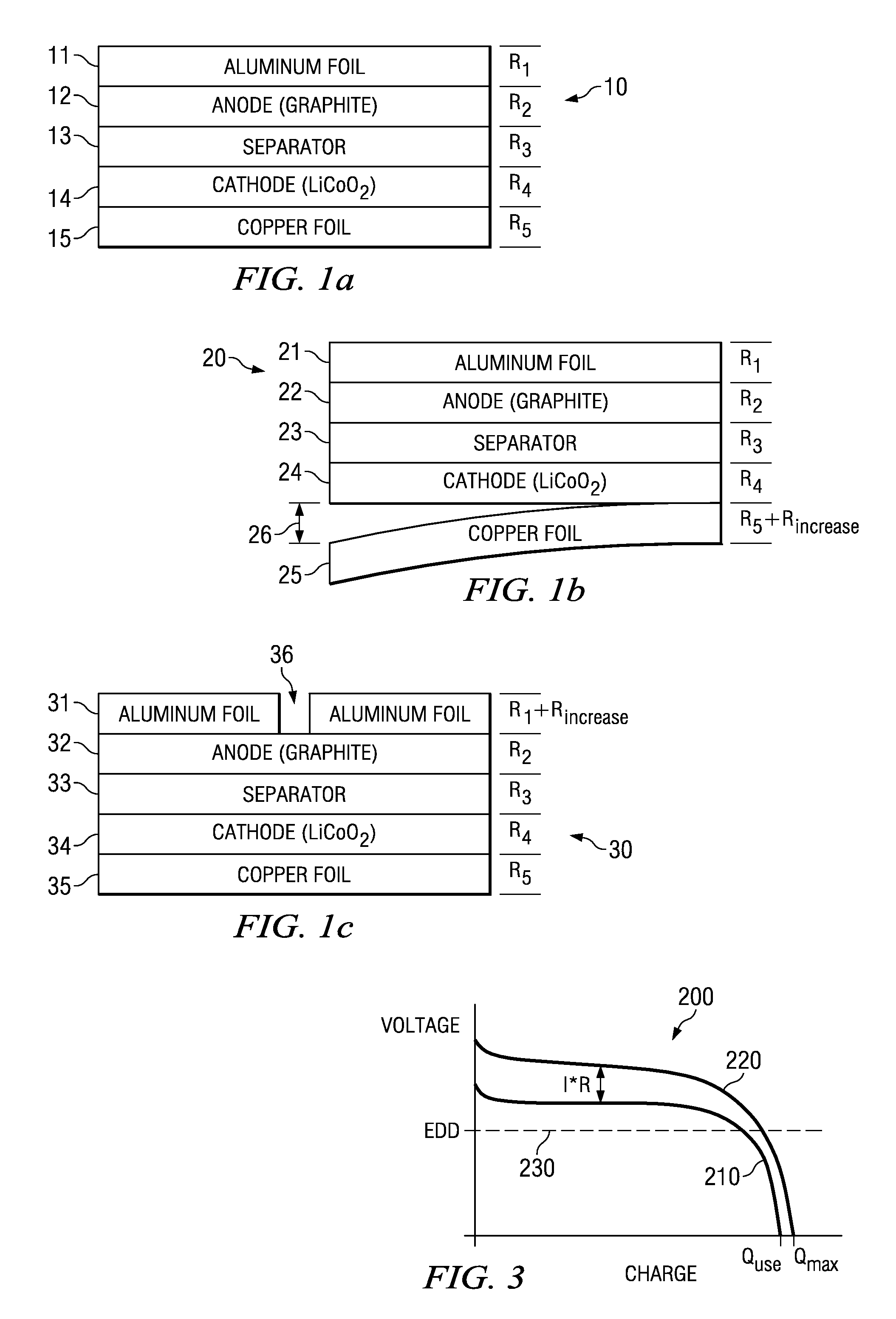
[0023]Turning to FIG. 1a, an exemplary battery cell 10 is depicted and includes an aluminum current collector 11, a graphite anode 12, a separator 13, a lithium based cathode 14, and a copper current collector 15. Each of the aforementioned layers has an associated impedance R1, R2, R3, R4, R5, respectively. Thus, the total internal impedance of battery cell 10 is described by the following equation:

Impedance=R1+R2+R3+R4+R5.

It has been determined that detachment or displacement of a significant structural element of a battery cell (e.g., metallic foil current collector 11 or 15, separator 13, or particle of active material) can cause a measurable change in cell impedance. FIG. 1b depicts an example of one such structural anomaly that leads to an increase in cell impedance. In particular, a battery cell 20 is depicted including an aluminum...


PUM


Abstract

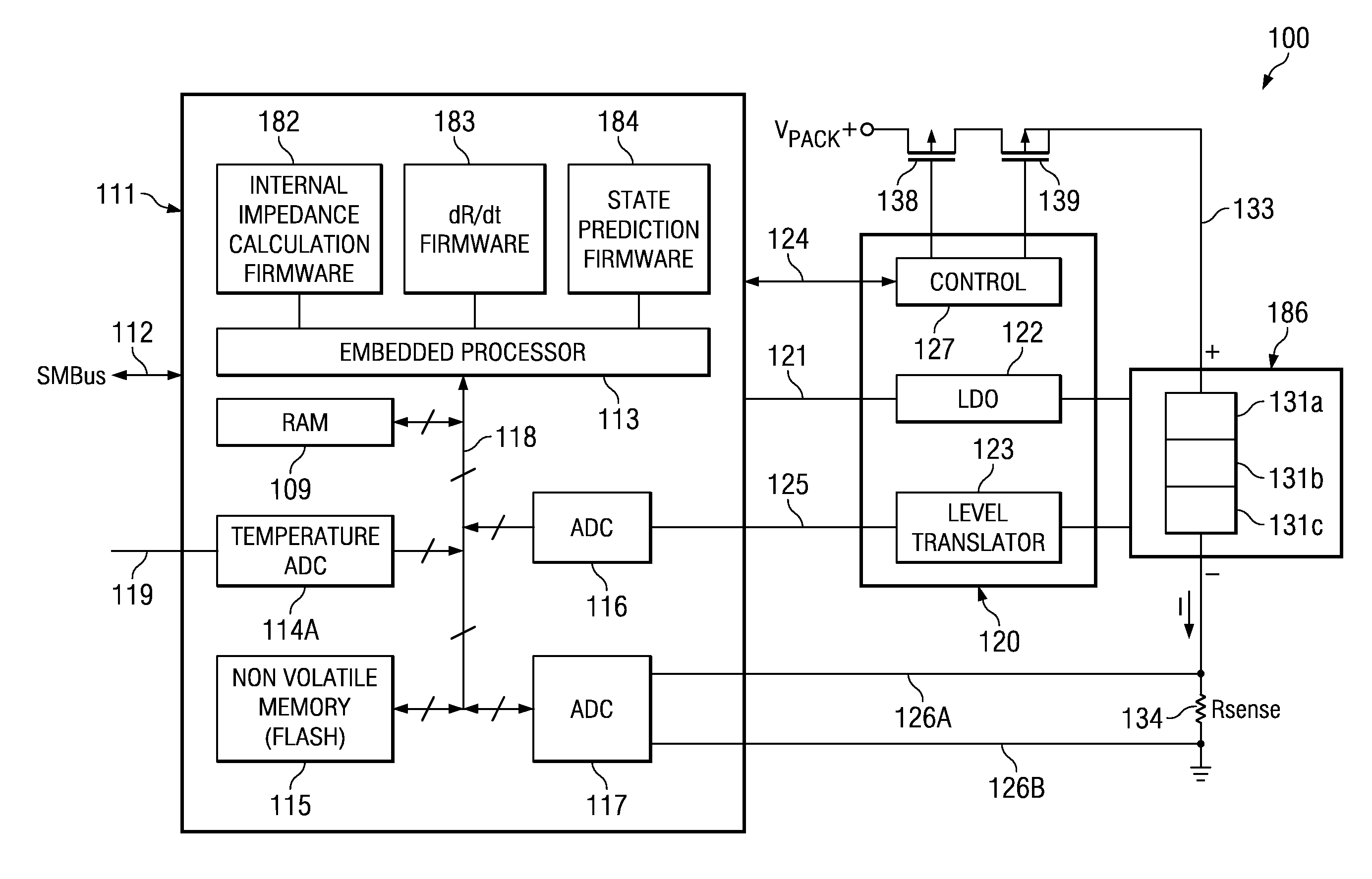
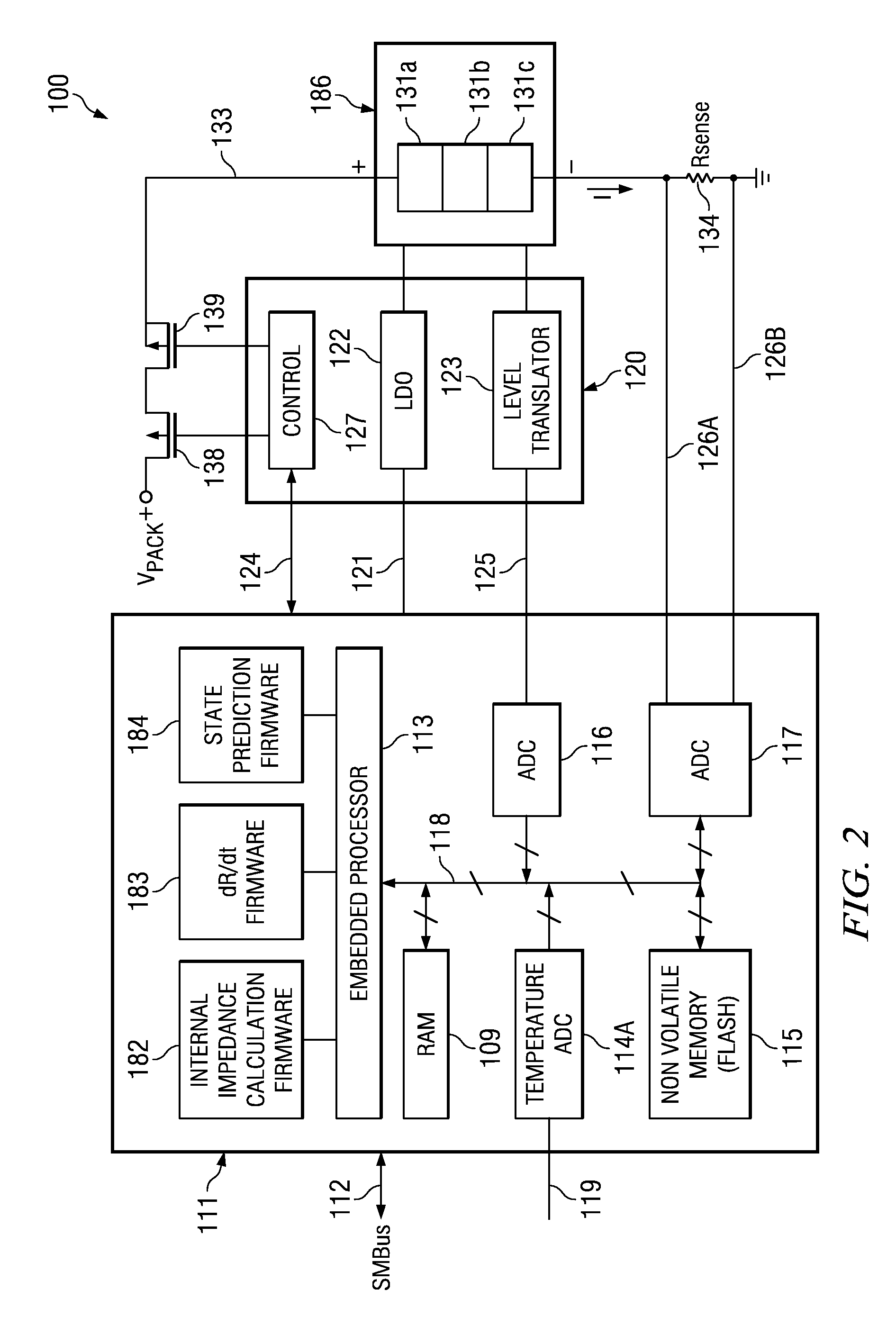
Various systems and methods for determining potential battery failure are disclosed. For example, some embodiments of the present invention provide battery systems that include a battery, an embedded processor and a computer readable medium. The computer readable medium includes instructions executable by the embedded processor to measure at least one characteristic of the battery; to calculate a rate of change of internal impedance of the battery based at least in part on the at least one characteristic of the battery; and to determine a potential failure condition based on the rate of change of internal impedance of the battery.

Description

BACKGROUND OF THE INVENTION[0001]The present invention is related to battery monitoring, and more particularly to systems and methods for detecting potential battery failure.[0002]A number of electronic devices utilize rechargeable batteries and associated charging systems. A rechargeable battery may be repeatedly charged and discharged over the course of its useful life. The process of charging and discharging is generally performed without incident other than the typical operational degradation of the battery over the course of operation. Indeed, most battery failure mechanisms operate to gradually decrease useful battery life and do not cause a safety hazard.[0003]At times one or more mechanisms may come into play that result in the catastrophic battery failure. Catastrophic battery failure may be benign resulting in, for example, an irreversible and immediate failure of the battery. Other times, however, a catastrophic battery failure may result in a fire with all of the problem...

Claims


Application Information

Patent Timeline
IPC IPC(8): G01R27/00
CPCG01R31/3648G01R31/389
Inventor BARSOUKOV, YEVGEN P.ELDER, GARRYQIAN, JINRONG
Owner TEXAS INSTR INC
Learn More