
Engine Control Apparatus

a control apparatus and engine technology, applied in the direction of electrical control, process and machine control, instruments, etc., can solve the problems of deviating even further from the target air-fuel ratio, undesirable for accurate air-fuel ratio control, etc., and achieve the effect of improving the accuracy of air-fuel ratio control

Inactive Publication Date: 2009-04-16
TOYOTA JIDOSHA KK
View PDF12 Cites 19 Cited by
  • Summary
  • Abstract
  • Description
  • Claims
  • Application Information

AI Technical Summary

Benefits of technology

[0012]According to this second aspect of the invention, an optimum correction coefficient so that the air-fuel ratio will not deviate from the target air-fuel ratio can be learned. As a result, it is possible to suppress variations in the air-fuel ratios or fuel injection quantities among cylinders or fuel injectors, and thus increase the accuracy of air-fuel ratio control.
[0014]Accordingly, learning is only performed while the engine is idling which enables it to be much simpler and the learning time drastically shortened compared to when learning is performed for the all of load regions.
[0016]During an in-cylinder fuel injection, the fuel pressure may also cause variation in the air-fuel ratios so performing learning with respect to each of a plurality of fuel pressures in this way enables air-fuel ratio control to be more accurate over a wider range.
[0017]Thus, the invention displays the excellent effects of enabling a fuel injection quantity correction to be performed in an appropriate manner during air-fuel ratio control, as well as the accuracy of the air-fuel ratio control to be improved.

Problems solved by technology

This variation is caused by individual differences due to, for example, injector manufacturing errors.
As a result, the air-fuel ratio deviates even farther from the target air-fuel ratio, which is undesirable for performing accurate air-fuel ratio control.

Method used


Image

  • Engine Control Apparatus
  • Engine Control Apparatus
  • Engine Control Apparatus

Examples


Embodiment Construction

[0032]In the following description and the accompanying drawings, the present invention will be described in more detail in terms of exemplary embodiments.

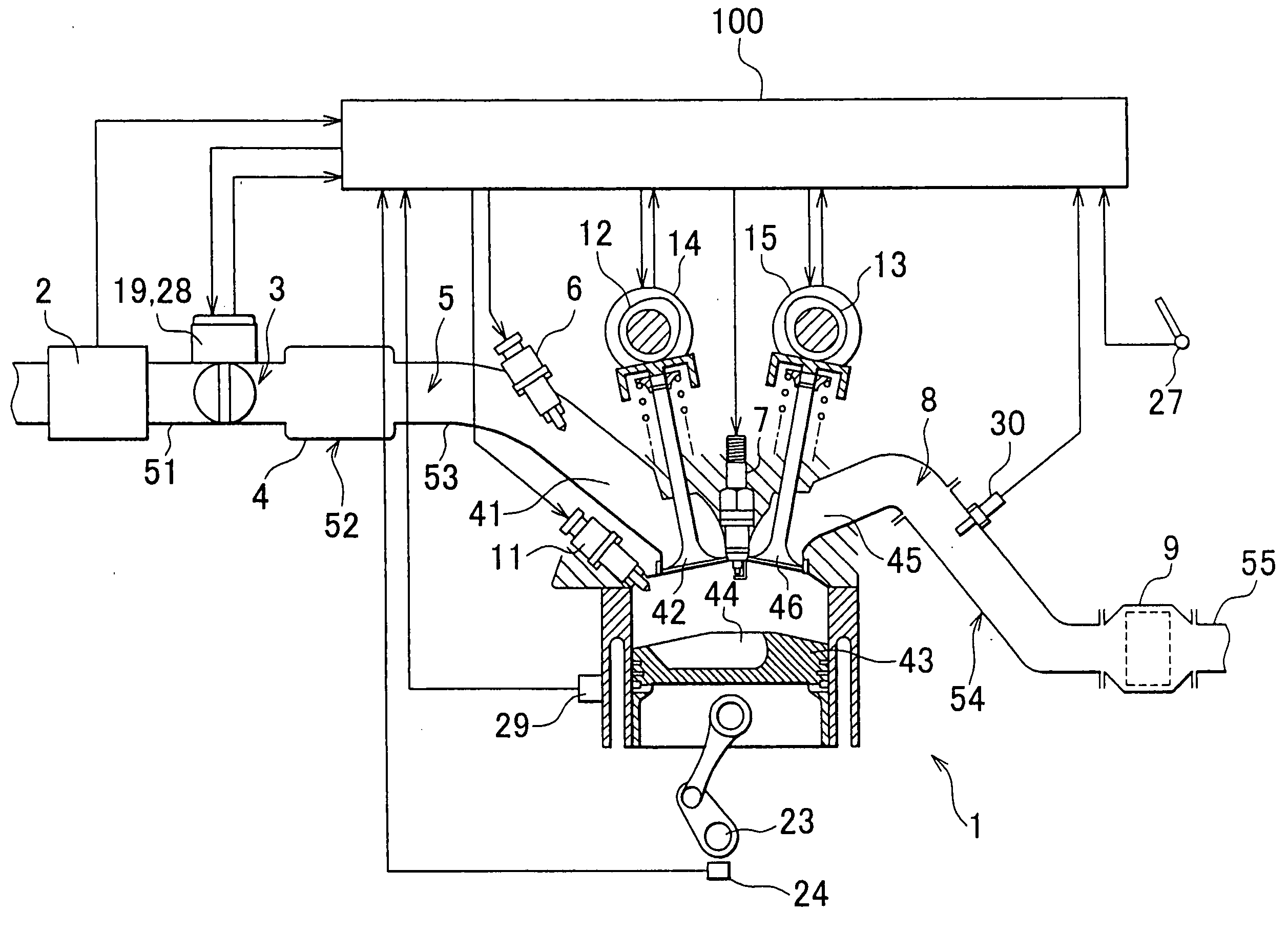
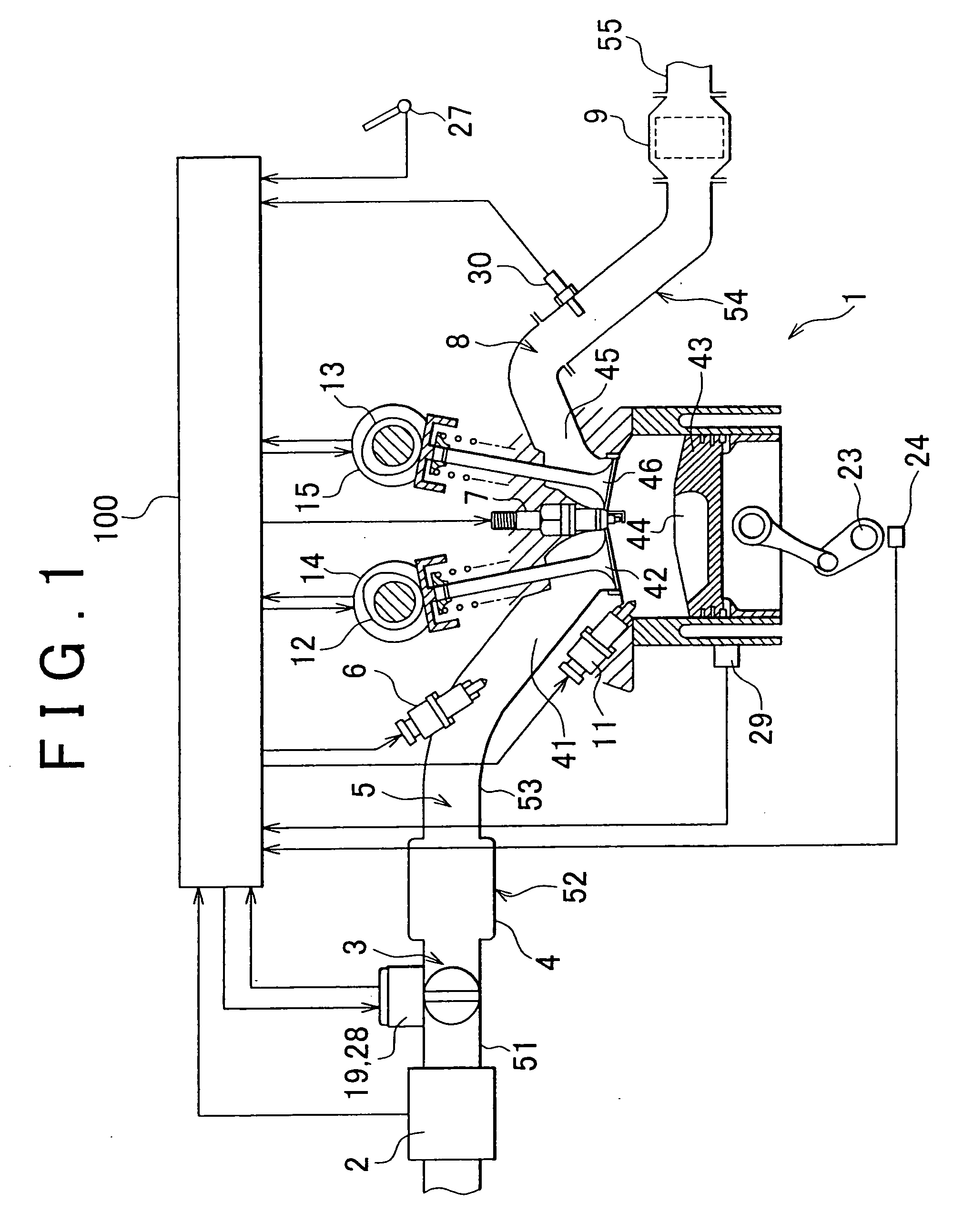
[0033]FIG. 1 shows a control system of an engine according to one example embodiment of the invention. The engine 1 shown in the drawing is a so-called dual fuel injector engine. In this example embodiment, the engine has four cylinders 4 (only one cylinder is shown in the drawing), though the number of cylinders is not particularly limited. An in-cylinder fuel injector 11 and an intake passage fuel injector 6 are provided for each cylinder. In this example embodiment, the engine 1 uses gasoline as fuel, though alcohol or a mixed fuel of alcohol and gasoline, a gas fuel such as CNG, or other fuel may also be used.

[0034]Air drawn in from an air cleaner, not shown, is distributed to the combustion chambers of the cylinders via an intake passage 5. The intake passage 5 is defined by an intake pipe 51, an intake manifold 52, and an in...


PUM


Abstract

A control apparatus of an engine that includes an intake passage fuel injector and an in-cylinder fuel injector according to the invention is characterised by further including correcting means for selectively increase-correcting or decrease-correcting a fuel injection quantity to bring an air-fuel ratio close to a predetermined target air-fuel ratio; and switching means for dividing an increase amount or decrease amount of the fuel injection quantity into a distribution ratio that is to be divided between the two fuel injectors, and when executing a correction by the correcting means, making one of the fuel injectors responsible for the larger part of a ratio, making the other fuel injector responsible for the smaller part of the ratio, and switching the fuel injector responsible fore the larger part of the ratio according to the operating state of the engine.

Description

BACKGROUND OF THE INVENTION[0001]1. Field of the Invention[0002]The invention relates to a control apparatus of an engine, and more particularly, to a control apparatus of an engine capable of executing both an intake passage fuel injection and an in-cylinder fuel injection.[0003]2. Description of the Related Art[0004]So-called dual fuel injector engines are known which are provided with an intake passage fuel injector for injecting fuel into an intake passage, and an in-cylinder fuel injector for injecting fuel into a cylinder. It is also well known that in this kind of dual fuel injector engine the total injection quantity during one injection cycle is divided between the two injectors and the distribution ratio of that fuel injection quantity is changed according to the operating state of the engine. Technology related to this is described in Japanese Patent Application Publication No. JP-A-2001-20837, for example.[0005]When executing air-fuel ratio control to bring the air-fuel ...

Claims


Application Information

Patent Timeline
IPC IPC(8): F02D41/30F02D41/04F02D41/34F02D45/00F02M63/00
CPCF02D41/1475F02D41/1482F02D41/1483Y02T10/44F02D41/2454F02D41/3029F02D41/345F02D41/2445F02D41/3094Y02T10/40
Inventor KANEKO, NAOYA
Owner TOYOTA JIDOSHA KK
Learn More