
Apparatus and Method for Delivering Electrical Signals to a Heart

Active Publication Date: 2009-04-16
IMPULSE DYNAMICS NV
View PDF9 Cites 43 Cited by
  • Summary
  • Abstract
  • Description
  • Claims
  • Application Information

AI Technical Summary

Benefits of technology

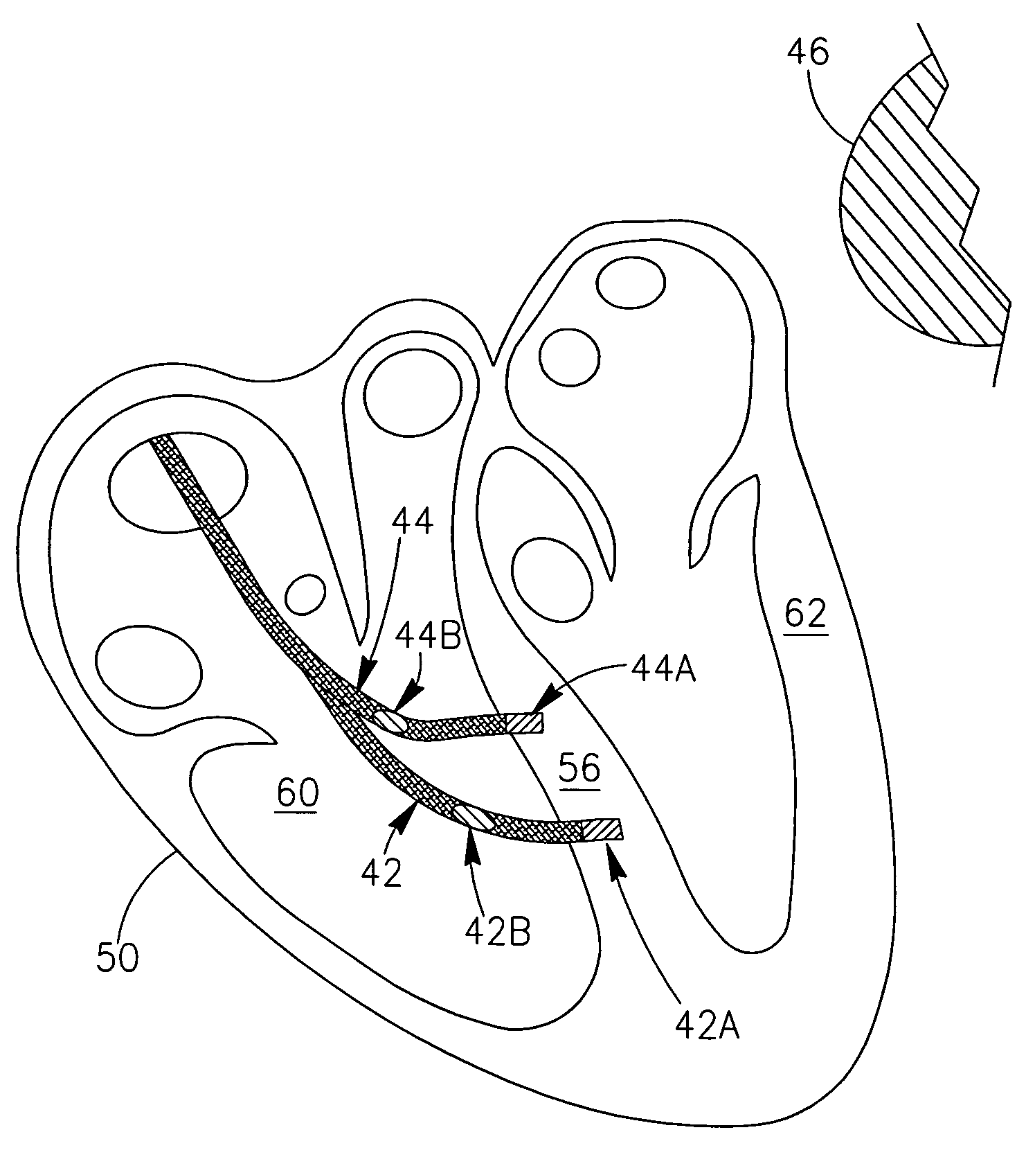
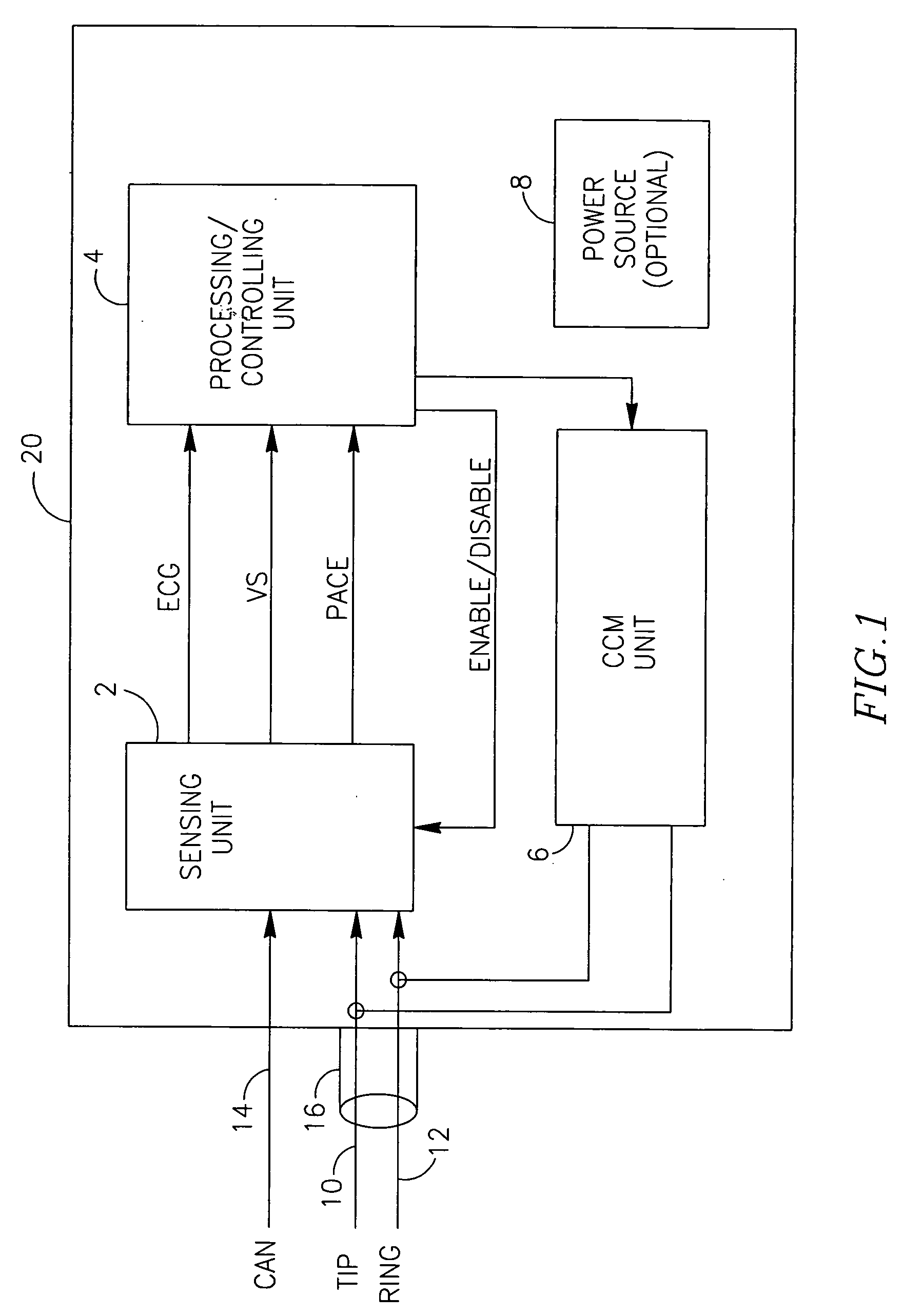
[0017]Another aspect of the present invention is that the recording of the global ECG signal enables the use of a simplified lead system in which there is no need for a sensing atrial lead. In such a simplified system, preferably (but not obligatorily) only one or two ventricular leads are used (and, preferably, the can of the implanted device), obviating the need for an atrial lead.
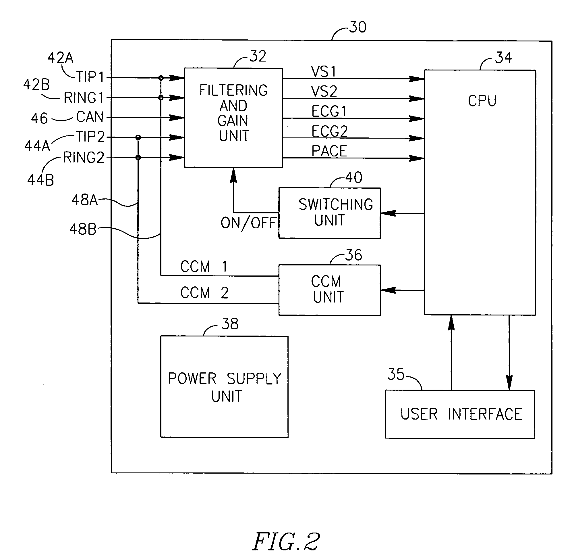
[0018]In accordance with another aspect of the present invention, the ECG signal (global signal) is used to differentiate between an electrical event due to an arrythmogenic atrium and an electrical event due to a distant ventricular ectopic beat. This is made possible due to an increased effective sensing range of unipolar differential recording performed between the distant electrode (preferably, but not obligatorily, the can of the CCM device) and one or more of the ventricular electrode(s), as compared to the very limited effective sensing range obtainable when recording locally sensed events (for example by using differential recording between two narrowly spaced electrode tip and ring, as is known in the art, or the like) using a ventricular electrode. This is enabled by the much larger distance between the can and the ventricular electrode(s). The probability of detecting a distant ectopic activity (such as, for example an ectopic event generated in the lateral part of a ventricular wall) is much larger using such globally recorded IECG than the probability of detecting such an event using ventricular local sensing with it's limited effective sensing range.
[0021]In accordance with another aspect of the present invention, the template may be a dynamic template which may be based on data continuously acquired from the patient and continuously adapting to time varying changes occurring in the heart of the patient. Such variations may include, inter alia, drug induced changes in cardiac electrical properties and activity, and changes in cardiac electrical waveforms due to a change in the physiological condition of the patient. Such changes may also include but are not limited to, physical stress related changes in heart rate or changes in electrical properties of cardiac muscle cell or in the properties of other electrically excitable cardiac tissues and / or pathways, hormonally induced changes due to intrinsic adrenergic or cholinergic effects, long term changes due to electrode movements or resistivity changes caused by deposition of extraneous material on the electrodes, changes in heart rate, changes in recorded waveforms due to artificial pacing by a pacemaker, or other such effects).
[0037]It is noted, that the devices and methods of the present invention provide the ability to sense and process signals within a single heart cycle almost immediately (or within a few milliseconds from the local sense event), enabling the identification of remote ectopic activity. It is not necessary to sense and process a whole QRS complex, allowing the making of a real-time decision within the current heart beat cycle (in other words, the devices and methods of the present invention enable real time decision making within each individual beat cycle). This is different from known ICD devices and methods, which normally take a decision whether or not to provide electrical therapy several seconds after sensing and processing multiple heart beat cycles.
[0039]It is noted that, in accordance with embodiments of the present invention, the devices and systems described herein may use other leads in the heart with a dedicated electrode or with an electrode that simultaneously serves for other purposes. Examples may include but are not limited to, a separate pacemaker lead or ICD lead, or a coronary sinus lead which may allow (possibly in parallel to its original function) connectivity to an electrode that provides signal(s) from outside the RV or LV, and thus allows better measurement of RV and LV remote ectopic activity. Such signals may be sensed and / or recorded between electrodes positioned outside the LV or RV chamber, or between one or more of such electrodes and the device's can, or between one or more such electrodes and an electrode positioned inside the RV or LV chambers.

Problems solved by technology

Timing of the delivery of CCM signals relative to the time of detection of locally sensed electrogram signals may present certain practical problems.
For example, triggering of the CCM signal by any locally detected depolarizing signals irrespective of the time of detection of the depolarizing signal within the cardiac beat cycle, may increase the probability of spurious detection of noise signals or of ectopic beats such as premature ventricular contractions (PVCs) or the like, which may lead to delivery of improperly timed and potentially arrhythmogenic CCM signals.
However, the use of multiple leads including an atrial lead complicates and often increases the time required for lead placement.
Currently, the treatment of such patients with supra-ventricular paroxysmal cardiac disorders present a challenge for CCM therapy as current ectopic beat detection methods and algorithms do not enable differentiating between temporally abnormal electrical activity due to an ectopic beat propagating from a lateral ventricular focus and an abnormally timed beat resulting from paroxysmal atrial activity.
As a result many of the patients with AF or belonging to a group with increased probability for developing AF are not candidates for CCM therapy using a CCM device.
Furthermore, if a patient already having an implanted CCM device develops AF, the CCM therapy is inhibited whenever an atrium is arrythmogenic.
This situation is undesirable, as the benefits of CCM therapy cannot be delivered to the ventricles while any atrial arrythmogenic activity is detected.
Another problem which may arise in the use of CCM devices is that a CCM device may often be implanted in a patient which has a previously implanted pacemaker.

Method used


Image

  • Apparatus and Method for Delivering Electrical Signals to a Heart
  • Apparatus and Method for Delivering Electrical Signals to a Heart
  • Apparatus and Method for Delivering Electrical Signals to a Heart

Examples


Embodiment Construction

Notation Used Throughout

[0101]The following notation is used throughout this document.

TermDefinitionBIVBiventricularCCMCardiac Contractility ModulatingCHFCongestive Heart FailureCSCoronary SinusGCVGreat Cardiac VeinHRHeart rateIECGIntra-cardiac ElectrocardiogramIEGMIntra-cardiac ElectrogramLUTLook Up TableLVLeft ventricleLVPLeft Ventricular PressuremsecmillisecondPACPremature Atrial ContractionPEPaced EventPVCPremature Ventricular ContractionRARight atriumRVRight ventricleSESensed EventSVCSuperior Vena CavaVSVentricular Signal

[0102]The application discloses, inter alia, devices systems and methods for delivering CCM signal(s) to a chamber of the heart undergoing electrical therapy (typically, one or more of the cardiac ventricles). The devices and methods are designed for inhibiting the delivery of the CCM signal(s) based on sensing electrical events at the cardiac chamber being therapeutically treated (regardless of electrical events in other cardiac chambers).

[0103]The devices and...


PUM


Abstract

Devices, systems and methods for controlling (inhibiting or enabling) the delivery of electrotherapeutic signals to a heart using sensing of local and / or global ECG signals to detect ventricular arrhythmia or indication of possible ventricular arrhythmia in the heart. The devices, systems and methods process the sensed signals and are capable of delivering electroptherapeutic signals to the heart in the presence of a supra-ventricular arrhythmia such as atrial fibrillation and atrial flutter, while inhibiting the delivering electroptherapeutic signals in the presence of PVCs and / or extopic beats, and / or ventricular arrhythmia. The electrotherapeutic signals may include, among others, pacing signals and cardiac contractility modulating signals.

Description

CROSS-REFERENCE TO RELATED US APPLICATIONS[0001]This application claims priority from and the benefit of U.S. Provisional Patent Application Ser. No. 60 / 714,460 filed Sep. 6, 2005, entitled “APPARATUS AND METHOD FOR DELIVERING OF CARDIAC CONTRACTILITY MODULATING SIGNALS TO A HEART”, incorporated herein by reference in its entirety.FIELD OF THE INVENTION[0002]The present invention relates generally to the field of methods and medical devices for modulating cardiac muscle activity and contractility and for cardiac pacing and more specifically to the field of methods and devices for delivering of cardiac contractility modulating signals to the heart of patients with supra-ventricular heart rate disorders.BACKGROUND OF THE INVENTION[0003]cardiac contractility modulating (CCM) devices are devices which modulate the activity of excitable tissues by application of non-excitatory electrical field signals to the excitable tissue through suitable electrodes in contact with the cardiac tissue....

Claims


Application Information

Patent Timeline
IPC IPC(8): A61N1/365
CPCA61B5/04525A61B5/0464A61N1/3622A61N1/3627A61B5/7217A61N1/368A61N1/3684A61N1/3702A61N1/36585A61N1/36843A61N1/36842A61B5/35A61B5/363
Inventor ROUSSO, BENNYEIZENBERG, NETANELPRUTCHI, DAVIDMIKA, YUVALSNIR, YEHUDA
Owner IMPULSE DYNAMICS NV
Learn More