
Television receiver and liquid crystal television receiver

a television receiver and liquid crystal technology, applied in the field of television receivers, can solve the problems of deteriorating the quality and reliability of the television receiver, the inability of the television receiver to meet the user's receiving ability, and the inability to receive the ability of the antenna. achieve the effect of increasing the degree of freedom of design and arrangemen

Inactive Publication Date: 2009-04-16
UNIVERSITY OF ELECTRO-COMMUNICATIONS +2
View PDF22 Cites 9 Cited by
  • Summary
  • Abstract
  • Description
  • Claims
  • Application Information

AI Technical Summary

Benefits of technology

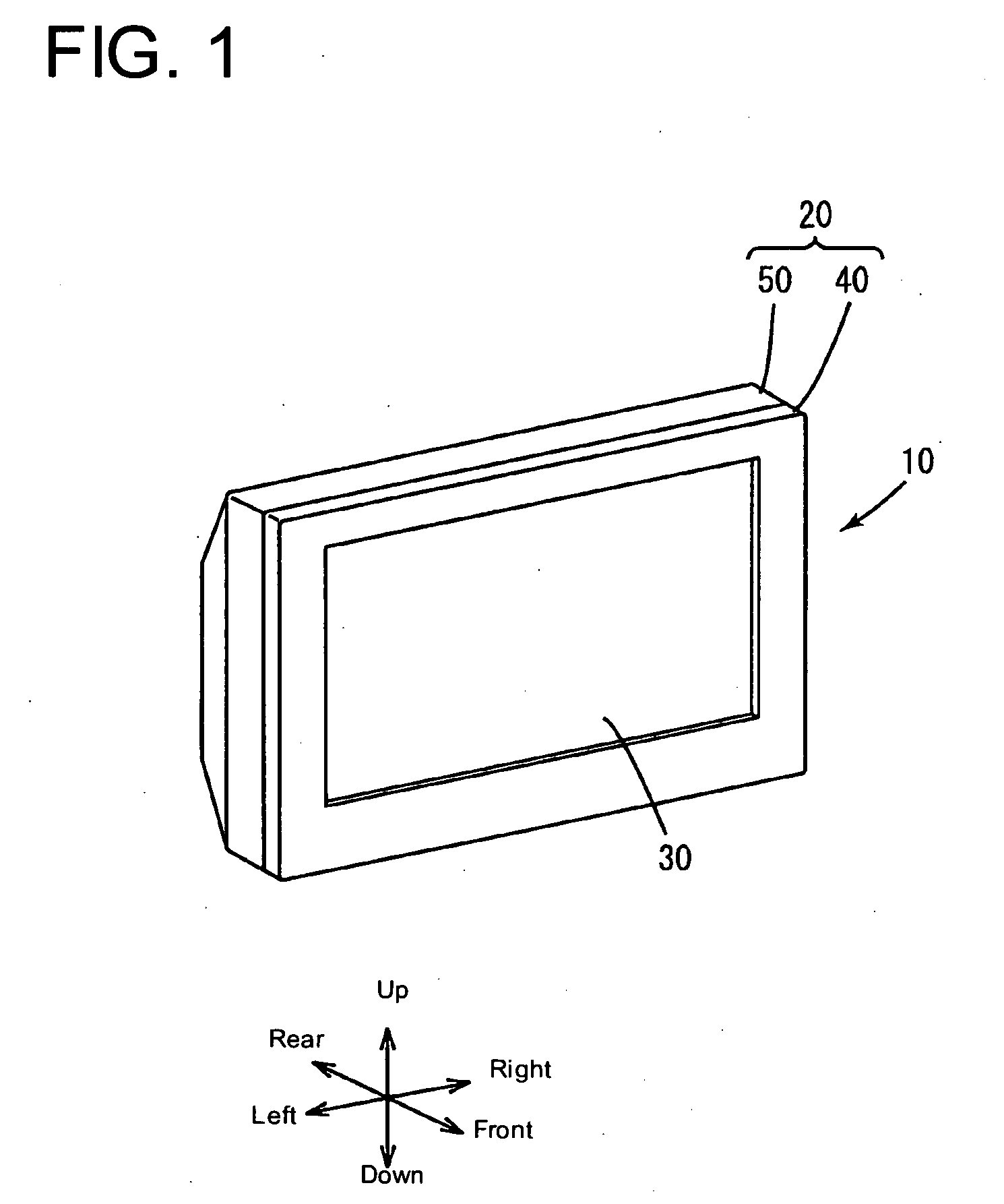
[0014]The present invention provides a television receiver capable of receiving desired broadcast signals in a satisfactory sensitivity and of not picking up unnecessary signals regardless of the direction of the television receiver, of being formed in a small thickness, of increasing the degree of freedom of designing and arrangement of component parts to be placed in a cabinet.
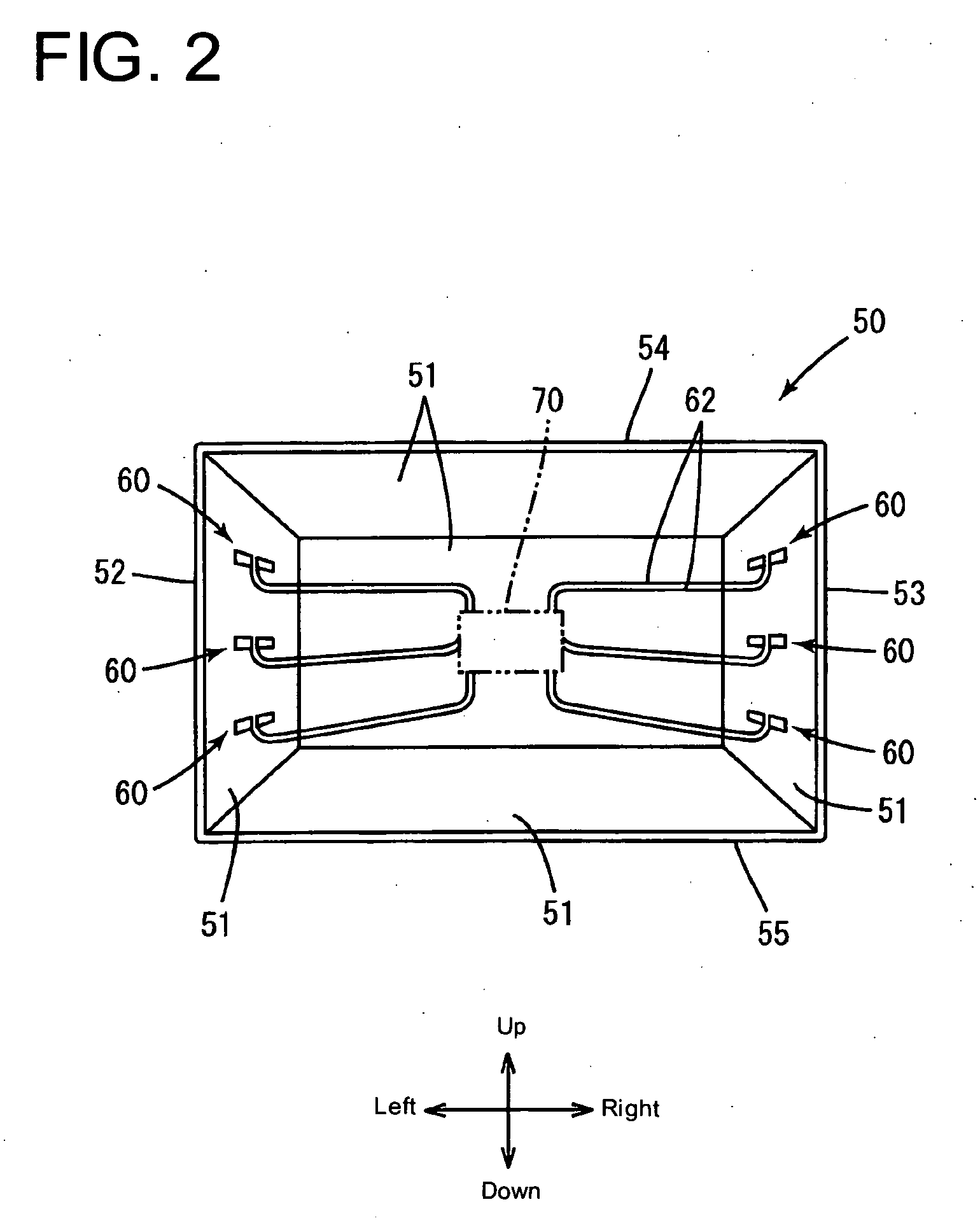
[0019]Each of the antennas may be formed by attaching a metal part having the shape of a dipole antenna to the surface. Since the antenna thus formed scarcely needs a space in the cabinet, the antenna is not an obstruct to other component parts and greatly contributes to forming the cabinet in a small thickness. Since the metal part of each antenna has the shape of a dipole antenna, the antenna can precisely receive broadcast signals.

Problems solved by technology

When a television receiver is provided with a built-in antenna, a problem arises in the receiving ability of the antenna.
Under such circumstances, if the sensitivity of the antenna to broadcast signals is greatly dependent on the direction of the television receiver, the quality and reliability of the television receiver will be markedly deteriorated.
Consequently, the television receiver cannot possibly satisfy a receiving ability required by the user.
Therefore, the thickness of the cabinet unavoidably needs to be considerably big to build the aperture waveguide antennas in the cabinet.
Thus, it is difficult for the digital television receiver to meet the recently desired reduction of the thickness of the television receiver.
Moreover, the large aperture waveguide antennas having a big height reduce the degree of freedom of designing and arranging other component parts to be placed in the cabinet.
Patent documents 3 to 5 do not solve the foregoing problem in the receiving ability of the television receiver.

Method used


Image

  • Television receiver and liquid crystal television receiver
  • Television receiver and liquid crystal television receiver
  • Television receiver and liquid crystal television receiver

Examples


Embodiment Construction

[0033]The detailed description set forth below in connection with the appended drawings is intended as a description of presently preferred embodiments of the invention and is not intended to represent the only forms in which the present invention may be constructed and or utilized. For purposes of illustration, programs and other executable program components are illustrated herein as discrete blocks, although it is recognized that such programs and components may reside at various times in different storage components, and are executed by the data processor(s) of the computers. Although the invention has been described in considerable detail in language specific to structural features and or method acts, it is to be understood that the invention defined in the appended claims is not necessarily limited to the specific features or acts described. Rather, the specific features and acts are disclosed as preferred forms of implementing the claimed invention. Therefore, while exemplary...


PUM


Abstract

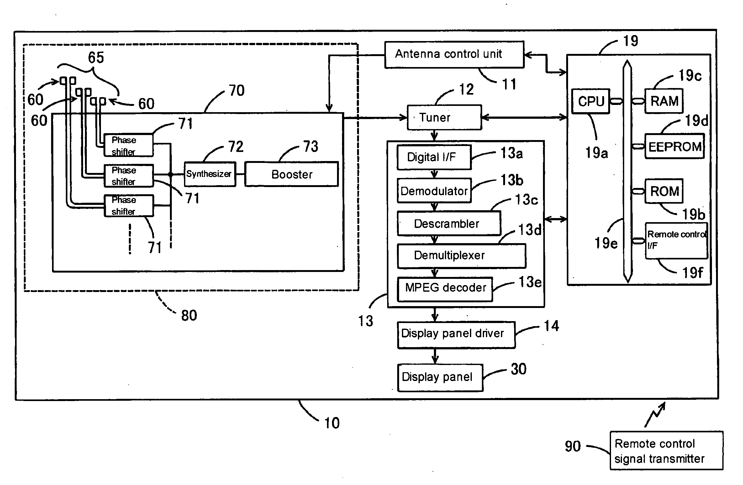
A television receiver having an antenna function for receiving broadcast signals includes an antenna group having plural variable directivities and including plural antennas formed in plural parts on inner and outer surfaces of walls of a cabinet or nonmetallic surfaces of component parts arranged in the cabinet so as to conform to the shapes of the corresponding surfaces, respectively, and a switching control unit capable of specifying a directivity for the antenna group to receive broadcast signals by the antenna group.

Description

CROSS REFERENCE TO RELATED APPLICATIONS[0001]The present application is related to the Japan Utility Model Application No. 2007-264357, filed Oct. 10, 2007 the entire disclosure of which is expressly incorporated by reference herein.BACKGROUND OF THE INVENTION[0002]1. Field of the Invention[0003]The present invention relates to a television receiver having an antenna function[0004]2. Description of the Related Art[0005]A television receiver mentioned in JP-A H11-308554 (Patent document 1) has a receiving unit including two loop antennas, namely, right and left loop antennas, affixed to a peripheral part of a front cabinet, the front surface of a CRT or the funnel of a CRT or incorporated into a front cabinet by insert molding.[0006]A digital television receiver disclosed in JP-A 2005-102142 (Patent document 2) has two electronically tunable aperture waveguide antennas built in or attached to receiving unit for phase synthesis diversity receiving.[0007]A portable telephone mentioned ...

Claims


Application Information

Patent Timeline
IPC IPC(8): H04N5/44H04B7/08H04B7/10H04N5/64
CPCH04N5/64H04N5/4401H04N21/426
Inventor NAKAJIMA, NOBUOGYODA, KOICHISHIBUYA, EIJIONOMATSU, TAKEHIROYOSHIMURA, HIDETO
Owner UNIVERSITY OF ELECTRO-COMMUNICATIONS
Learn More