Manufacturing method of tire forming mold and tire forming mold

a tire forming mold and manufacturing method technology, applied in the field of manufacturing methods, can solve the problems of difficulty in finishing the end surface of the sector at a high precision, increase the number of parts, and reduce the working number of parts. , the effect of high precision

Inactive Publication Date: 2009-04-16
TOYO TIRE & RUBBER CO LTD
View PDF2 Cites 3 Cited by
  • Summary
  • Abstract
  • Description
  • Claims
  • Application Information

AI Technical Summary

Benefits of technology

The present invention provides a manufacturing method for a tire forming mold that can easily divide an annular mold portion and closely attach the end surfaces of sectors to each other at a high precision without carrying out lapping work. This is achieved by incorporating a circular arc shaped inner segment divided by a non-flat surface division, which simplifies the process and reduces the risk of working error. The non-flat surface division aims to divide the inner segment by its shorter peripheral length than the annular mold portion, and the first and second segment pieces obtained by this division are incorporated into the inner peripheral sides of the back segments. This reduces the number of parts and working number and also helps to prevent rubber burr and breakage of the frame portion and blade. The non-flat surface divided surfaces are arranged in the end surface of the sector to closely attach the end surfaces of the sectors to each other.

Problems solved by technology

In the piece type, it is possible to discharge an air from a lot of small gaps formed between the pieces, however, there is a tendency that the number of the parts is increased.
In the segmented type tire forming mold, since an end surface of the sector travels down through the frame portion forming a transverse groove or cuts across the blade in cooperation with a complexity of a tread pattern in the case of dividing the annular mold portion by a flat surface (dividing by a flat surface including a tire axis), a breakage of a thinned frame portion and a shortened blade comes into problem.
However, since the non-flat surface division has a high difficulty for working in comparison with the flat surface division, it is not easy to finish the end surface of the sector at a high precision.
However, this apparatus is provided with a large-sized rotary table for retaining the ring-shaped casting, which is a heavy load, so as to move in a circumferential direction, and a large-sized NC machine, and thus requires a large-scaled expensive equipment.
However, since a working error is generated in each of the end surfaces in the case of working the end surfaces of a pair of pieces which are individually manufactured, a gap tends to be formed at a time of confronting them.
Accordingly, it is necessary to carry out a lapping work after working the end surface as the non-flat surface, which raises a problem that the work is complicated.

Method used


Image

  • Manufacturing method of tire forming mold and tire forming mold
  • Manufacturing method of tire forming mold and tire forming mold
  • Manufacturing method of tire forming mold and tire forming mold

Examples


Embodiment Construction

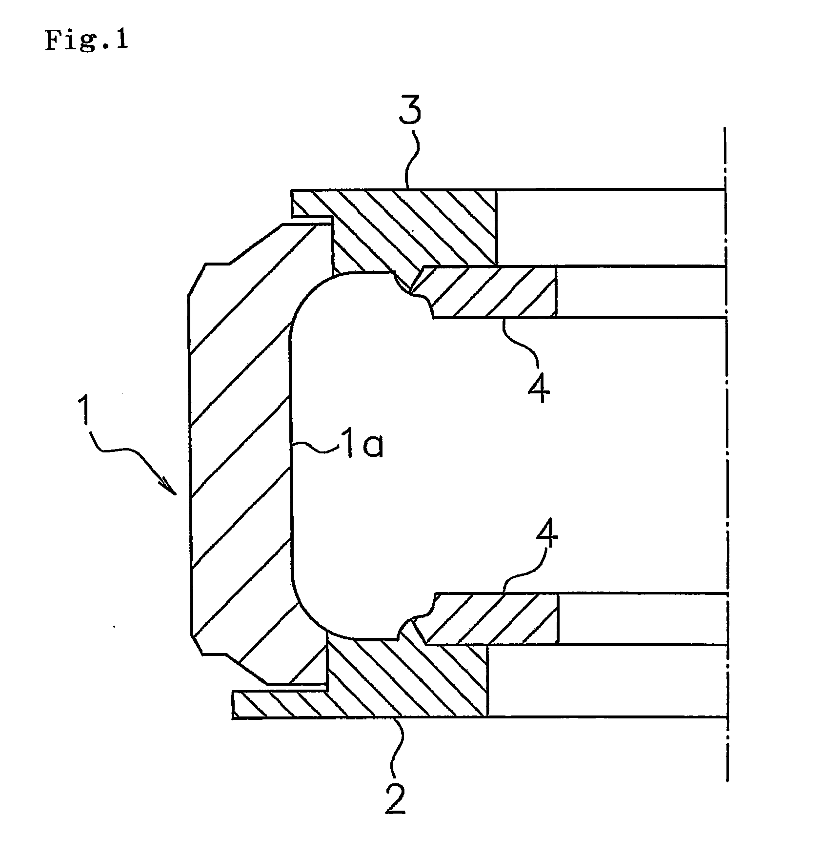
[0034]An embodiment of the present invention will be explained with reference to the drawings. FIG. 1 is a vertical cross sectional view of an example of a tire forming mold in accordance with the present invention, and shows a mold clamping state. In the FIG. 1, a green tire (not shown) is set in such a manner that a tire axial direction is arranged up and down. In other words, a right direction in FIG. 1 corresponds to an inner side in a tire diametrical direction, and a left direction corresponds to an outer side in the tire diametrical direction. The tire forming mold (hereinafter, there is a case of being simply referred to as a forming mold) is the segmented type.

[0035]The forming mold in accordance with the present embodiment is provided with an annular mold portion 1 with which a tread portion of a tire is brought into contact, a lower mold portion 2 with which a side wall portion in a lower side is brought into contact, and an upper mold portion 3 with which a side wall por...


PUM

PropertyMeasurementUnit
concavo-convex shapeaaaaaaaaaa
shapeaaaaaaaaaa
structureaaaaaaaaaa

Abstract

A manufacturing method of a tire forming mold in which an annular mold portion is constituted by a combination of sectors includes a step of manufacturing a circular arc shaped inner segment provided with a concavo-convex shape, a step of dividing the inner segment by a non-flat surface division so as to obtain a first segment piece and a second segment piece, and a step of incorporating the first segment piece into an inner peripheral side of a back segment of one sector out of a pair of sectors which are adjacent to each other in the tire circumferential direction, incorporating the second segment piece into an inner peripheral side of a back segment of the other sector, and arranging the non-flat surface divided surface in an end surface of the sector.

Description

BACKGROUND OF THE INVENTION[0001]1. Field of the Invention[0002]The present invention relates to a manufacturing method of a tire forming mold for vulcanization forming a tire and the tire forming mold.[0003]2. Description of the Related Art[0004]The tire forming mold mentioned above is constructed by combining a plurality of mold portions, and can be roughly classified into a two-piece type and a segmented type based on the mold structure. In the latter, an annular mold portion coming into contact with a tread surface of a tire is constructed by a plurality of sectors divided in a tire circumferential direction, and an inner peripheral surface of each of the sectors is provided with a frame portion for forming a groove portion and a concave portion for forming a land portion. Further, in the case where a notch called as a sipe is formed in the land portion, a thin blade is provided within the concave portion. The sectors are away from each other in a mold open state, however, the s...

Claims


Application Information

Patent Timeline
Patent Type & Authority Applications(United States)
IPC IPC(8): B29C33/00
CPCB29D30/0629
Inventor HYODO, MASAKI
Owner TOYO TIRE & RUBBER CO LTD
Why Eureka
Try Eureka