
Antenna substrate for non-contact communication apparatus and non-contact communication apparatus

a technology of non-contact communication apparatus and antenna substrate, which is applied in the direction of screened loop antenna, transmission, instruments, etc., can solve the problems of increasing the cost of the device, and the general cost of the magnetic sheet, so as to increase the overall thickness of the device and the device cost increase

Inactive Publication Date: 2009-04-09
SONY CORP
View PDF3 Cites 30 Cited by
  • Summary
  • Abstract
  • Description
  • Claims
  • Application Information

AI Technical Summary

Benefits of technology

[0007]However, the magnetic sheet is generally expensive, which causes a cost increase of the device. Further, the insertion of the thick magnetic sheet leads to an increase in an overall thickness of the device.
[0008]It is desirable to provide an antenna substrate for a non-contact communication apparatus and a non-contact communication apparatus which enable a stable non-contact communications with closely arranged antenna coils by suppressing the fluctuations in antenna characteristics due to the distance between antennas, without using any magnetic sheet.
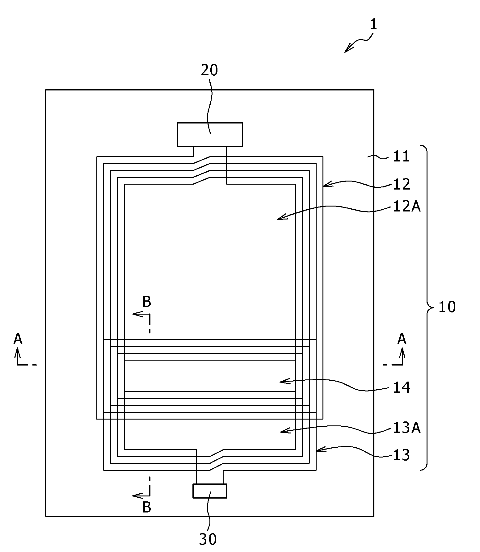
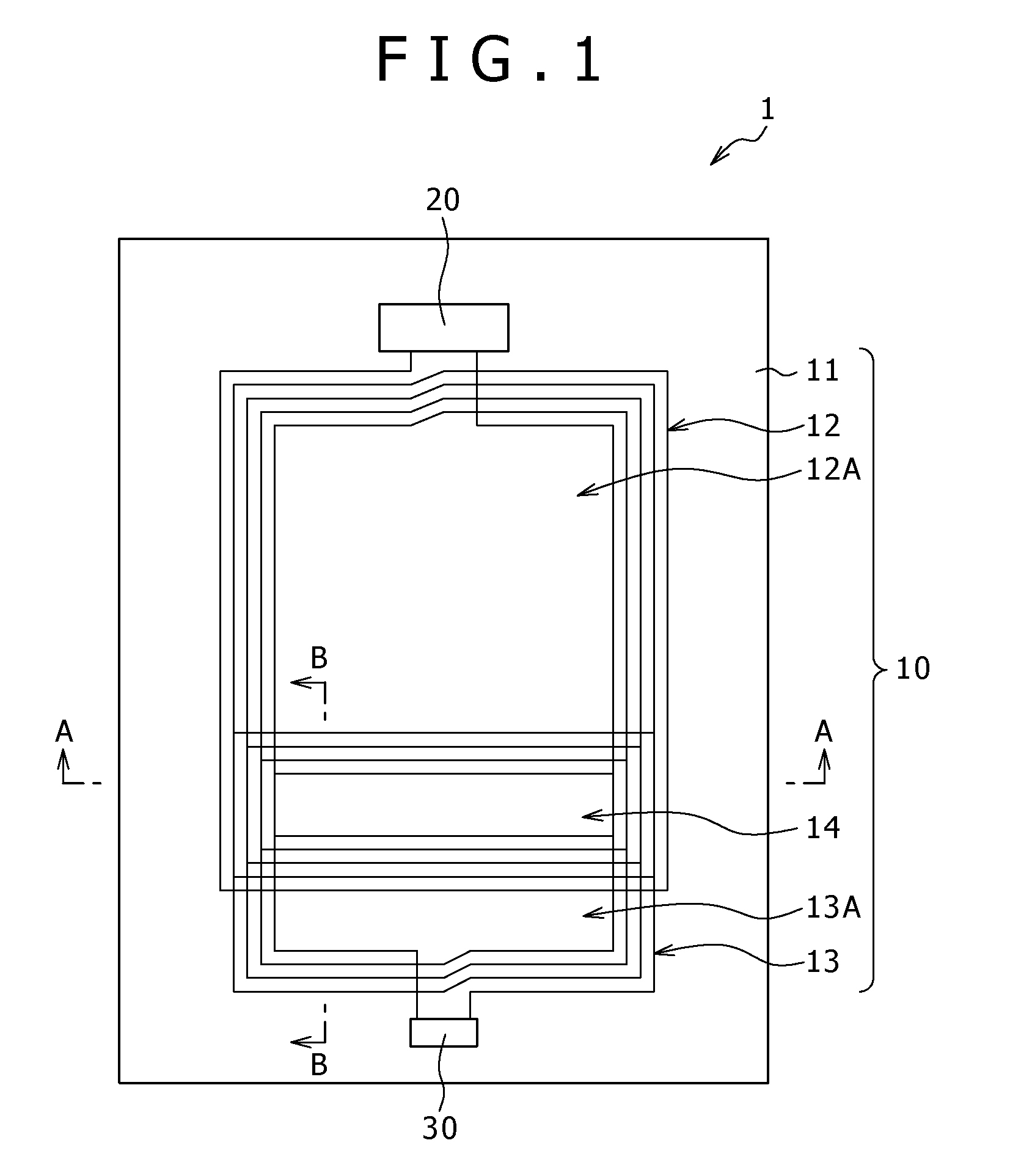
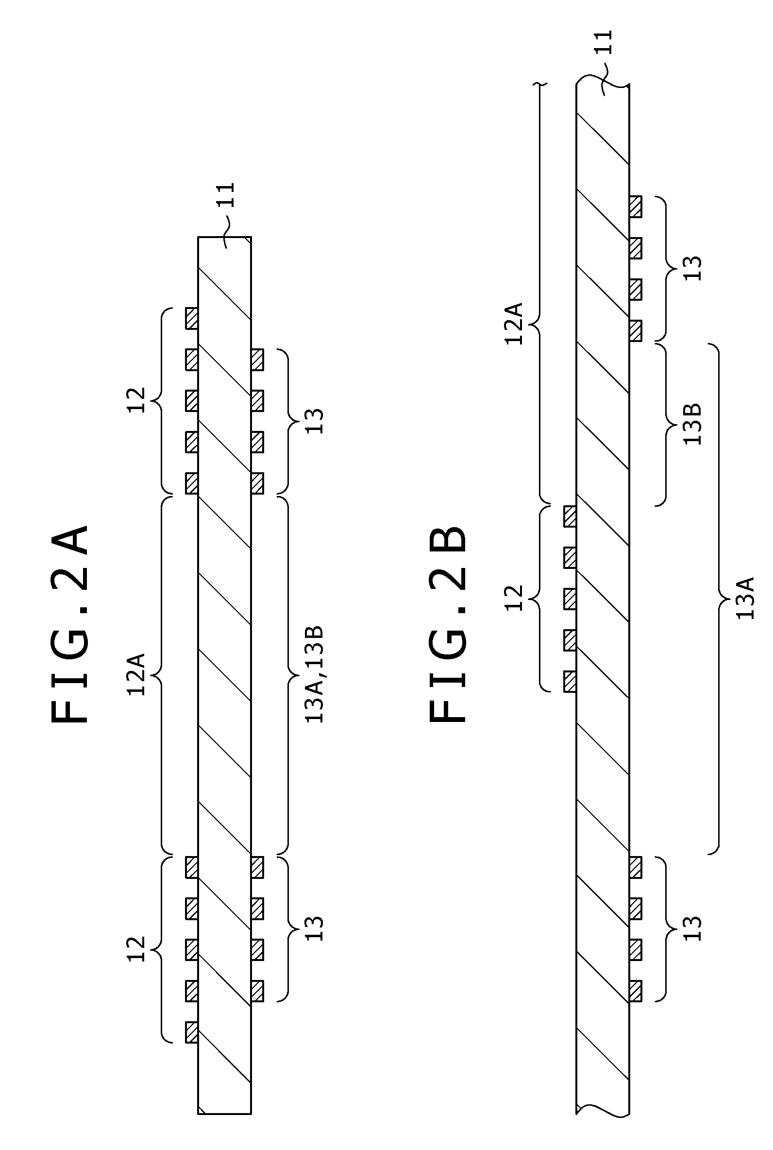
[0011]In the antenna substrate for a non-contact communication apparatus and the non-contact communication apparatus according to embodiments of the invention, the auxiliary coil having the opening having a smaller opening area than the opening of the antenna coil is insulated and isolated from the antenna coil, and arranged so that the second opening is opposed to a part of the first opening when viewed from a direction orthogonal to the surface of the support substrate. It is therefore capable of reducing the total amount of magnetic fields flowing generated from the antenna coil into the second opening of the auxiliary coil when the predetermined signal is applied to the antenna coil. This enables a reduction of the magnetic coupling between the antenna coil and the auxiliary coil, whereby the shortening the communicable distance between the antenna and the third coil can be suppressed. By properly adjusting the resonance frequency of the antenna coil and the resonance frequency of the auxiliary coil, for example, when a metal substance is arranged on a back surface of the support substrate and the antenna coil is closely arranged on the surface of the support substrate while applying electric power and a transmission signal to the antenna coil, an amount of reduction in an effective self-inductance of the third antenna coil due to an influence of the metal substance can be cancelled by increasing the effective self-inductance of the third antenna coil due to an influence of the auxiliary coil.
[0012]Thus, the antenna substrate for a non-contact communication apparatus and the non-contact communication apparatus according to embodiments of the invention, the auxiliary coil having the opening having a smaller opening area than the opening of the antenna coil is insulated and isolated from the antenna coil and arranged so that the second opening is opposed to a part of the first opening when viewed from the direction orthogonal to the surface of the support substrate. As a result, by properly adjusting the respective resonance frequencies of the antenna coil and the auxiliary coil, the fluctuations in antenna characteristics due to the distance between antennas can be suppressed without using any magnetic sheet. As a result of this, a stable non-contact communication with antenna coil which is closely arranged can be performed.

Problems solved by technology

However, the magnetic sheet is generally expensive, which causes a cost increase of the device.
Further, the insertion of the thick magnetic sheet leads to an increase in an overall thickness of the device.

Method used


Image

  • Antenna substrate for non-contact communication apparatus and non-contact communication apparatus
  • Antenna substrate for non-contact communication apparatus and non-contact communication apparatus
  • Antenna substrate for non-contact communication apparatus and non-contact communication apparatus

Examples


example

[0048]An example of the non-contact communication apparatus 1 of the above embodiment will be described below.

[0049]In the example, the inductance of the antenna coil 12 was set to approximately 1.2 μH. The inductance of the antenna coil 112 of the opposed card 100 was set to approximately 1.2 μH. Accordingly, the resonance frequency (communication frequency) of the antenna coils 12 and 112 was set to approximately 13.56 MHz. The inductance of the auxiliary coil 13 was set to approximately 1.6 μH, and the capacitance of the capacitance element 30 was set to 82 μF. Accordingly, the resonance frequency f0 of the resonator constructed from the auxiliary coil 13 and the capacitance element 30 was set to approximately 14 MHz (>13.56 MHz). The ratio of the area of the opposed region 14 (the opposing area) to the opening area of the opening 13A was substantially 50%.

[0050]FIG. 6 shows the inductance of the non-contact communication apparatus 1 when the distance D between antennas is change...


PUM


Abstract

An antenna substrate for a non-contact communication apparatus includes a support substrate and an antenna coil provided on or inside of the support substrate. The antenna coil has a first opening and an auxiliary coil. The auxiliary coil has a second opening which has an opening area smaller than the first opening. The auxiliary coil is insulated and isolated from the antenna coil, and arranged so that the second opening is opposed to a part of the first opening when viewed from a direction orthogonal to a surface of the support substrate.

Description

CROSS-REFERENCE TO RELATED APPLICATIONS[0001]The present application claims benefit of priority of Japanese patent Application No. 2007-260154 filed in the Japanese Patent Office on Oct. 3, 2007, the entire disclosure of which is incorporated herein by reference.BACKGROUND OF THE INVENTION[0002]1. Field of the Invention[0003]The present invention relates to an antenna substrate for a non-contact communication apparatus provided with two coils insulated and isolated from each other.[0004]2. Description of Related Art[0005]In a short-range wireless communication of inductor coupling type, non-contact communication is performed by bringing two antenna coils close to each other so as to establish a magnetic coupling between these two antenna coils. However, when a metal substance is arranged on the back side of either one of these antenna coils, the metal substance becomes closer to the other antenna coil as these two antenna coils are brought closer to each other. Consequently, the eff...

Claims


Application Information

Patent Timeline
IPC IPC(8): H01Q7/00H01Q1/24
CPCG06K19/07749H01Q7/00H01Q1/2225G06K19/07767H01Q7/04H04B5/26
Inventor MIZOROKI, TAKASHIMORI, KOHEI
Owner SONY CORP
Learn More