Interlocking container assembled to form useful structures

a technology of interlocking containers and containers, applied in the field of containers, can solve the problems of reducing the cost of transporting materials to a reprocessing site, reducing the number of containers, so as to achieve the effect of convenient piercing, removing or separating

Inactive Publication Date: 2009-04-09
INDAL ALCHEMY KITCHEN
View PDF24 Cites 100 Cited by
  • Summary
  • Abstract
  • Description
  • Claims
  • Application Information

AI Technical Summary

Benefits of technology

[0008]Accordingly, the container may be of any useable size, but embodiments sized in the range of popular consumer containers are advantageous. The container may be formed from a wide variety of materials, including paper, wood, pressed pulp, plastic, metal, or plasticised or plastic coated material. Plastic is a preferred material for drink containers, and thus the container of the present invention is advantageously made with plastic, for its acceptability from a consumer standpoint, for its physical properties with respect to manufacturing, and for its structural strength and durability.
[0009]The body of the container may have any of a variety of shapes with an internal volume. Advantageous shapes include those most commonly found for containers of consumer products, including elongated cylindrical or rectangular configurations. The latter has the additional advantage of imparting addition strength to an assemblage of containers.
[0010]In accordance with an embodiment of the invention, at least two lateral mating and interlocking portions extend along the side of a container. Interlocking designs include dovetails, or any other shaped profile which engages in a like manner. Specifically, in accordance with the invention, an elongated engaging portion of one container slideably engages an elongated engaging portion of another container along the vertical axis of the container. Containers thus joined cannot be separated by applying a force perpendicular to the vertical axis without deformation or damage to the engaging portions. To facilitate repetitive interlocking on all four sides with a single container design, it is advantageous to have opposing sides that are either both male engaging, or both female engaging.
[0015]Further in accordance with the invention, an end wall may be provided at the terminal end of the inwardly extending aperture at the trailing end of the container. The wall is operative to retain flowable materials within the container. The wall may be provided with a weakened portion, whereby the wall may be easily pierced, split, pushed aside or removed, as by pushing with a finger, rod, or other object. In so doing, containers connected vertically as described above may be coupled to a supply of flowable material, using threaded connectors or adapters, and the connected containers thus used in the manner of piping to convey the flowable materials from a source to a destination. Further, end wall portions of the lateral couplings described above may also be provided with weakened portions, whereby the flowable material may be tapped at various points along the pipe.

Problems solved by technology

The disadvantages of landfilling solid consumable waste, and plastic containers in particular, are well known.
There are numerous problems with recycling plastics, however.
These include the need to carefully sort different types of plastic, the cost of transporting the material to a reprocessing site, the high energy required for melting and reprocessing the material, and the difficulties associated with separating biodegradeable plastics, or plastics containing dyes or additives.
A challenge remains, however, to find sufficient demand for containers in their existing form, so that large numbers of them may be reused.
In Garpow and Brown, the utility of the containers are limited in that the containers may be joined by mating portions, but are easily separated.
Thus, the prior art provides for lateral connections, and a limited set of vertical connections, but no other connection possibilities.
As such, the range of items that can be fabricated in the prior art is too limited.

Method used


Image

  • Interlocking container assembled to form useful structures
  • Interlocking container assembled to form useful structures
  • Interlocking container assembled to form useful structures

Examples


Embodiment Construction

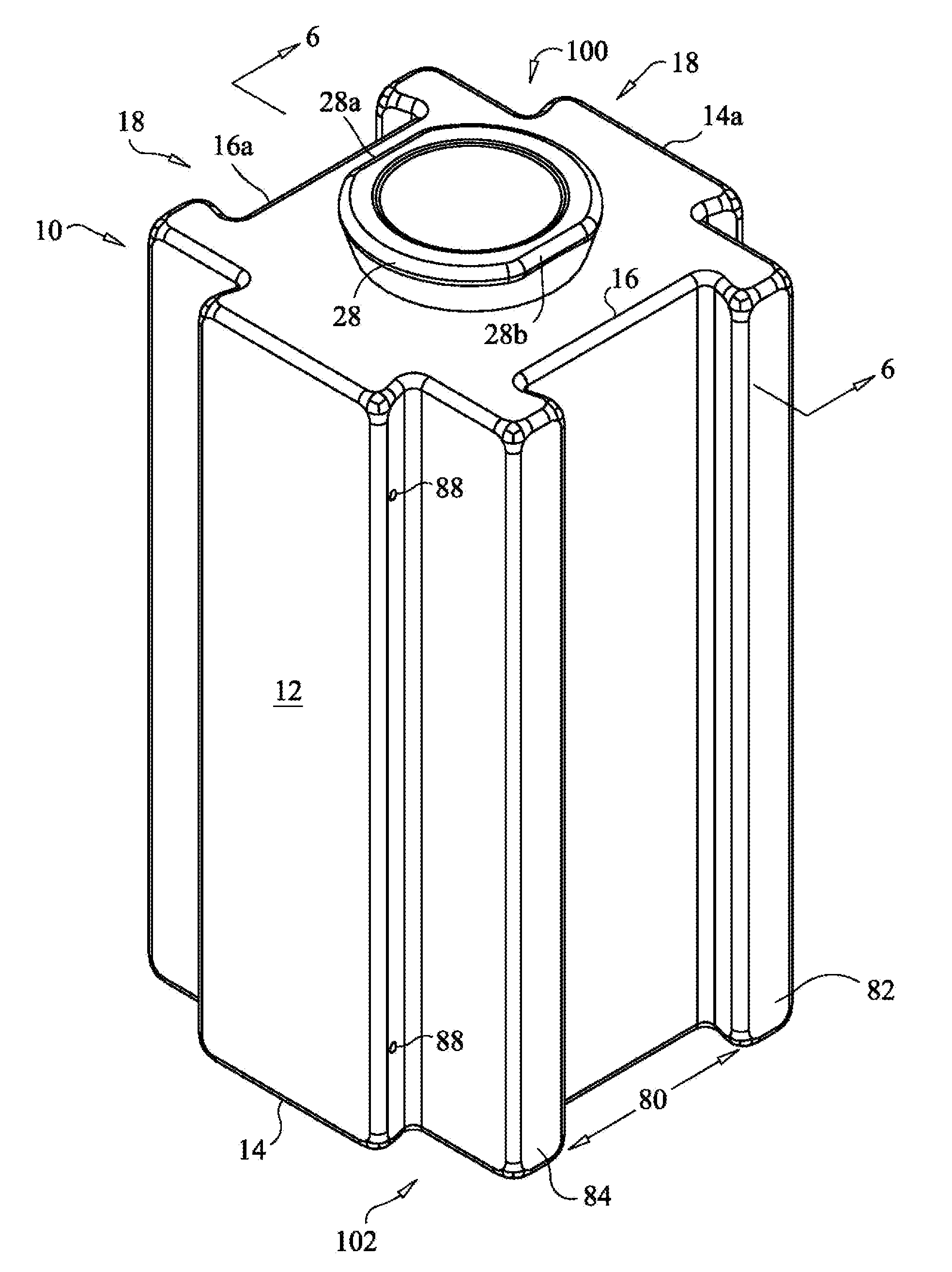
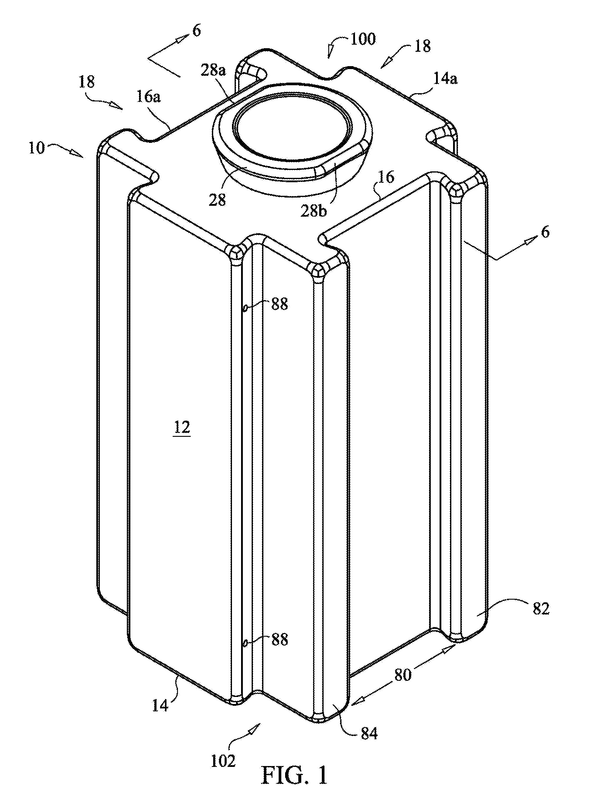
[0033]Referring now to the figures in which like reference numerals refer to like elements, an exemplary container 10 in accordance with the invention is illustrated in FIG. 1. Container 10 has an inner chamber 12 operative to contain, and as described further below, transport flowable materials, such as liquids, pourable solids, and gases. It is a goal of the invention to provide a container which is favored by consumers, whereby consumable producers are motivated to switch from non-reusable containers to containers in accordance with the invention, whereby the environmental benefits of reuse may be realized.

[0034]Accordingly, the container may be of any useable size, but embodiments sized in the range of popular consumer containers would be advantageous. The container may be formed from a wide variety of materials, including paper, wood, pressed pulp, plastic, metal, or plasticised or plastic coated material. Plastic is a preferred material for drink containers, and thus the conta...


PUM


Abstract

An apparatus for containing and conducting flowable materials, including liquids, pourable solids, or gases, the apparatus having mateable dovetails on four sides, and mateable screw engagements at the top and bottom. The screw engagements are operative to maintain a sealed connection between successive containers, and contain barriers which are adapted to be removed, whereby the material may flow from one interconnected container to the next, in the manner of piping. A lateral connection may additionally be formed by mating portions at the leading and trailing ends of vertically connected containers. A perpendicular connection is formed by interlocking an engaged cap of a first container with a lateral interlocking portion of a like container.

Description

CROSS REFERENCE TO RELATED APPLICATIONS[0001]Commonly assigned application Ser. No. 11 / 839,256 discloses a reusable container embodying certain aspects of the present invention, and is hereby incorporated by reference in its entirety.FIELD OF THE INVENTION[0002]The present invention relates to a container for flowable materials, mateably engageable laterally and vertically with like containers. Connections are provided whereby successive containers may be joined to create furniture, building structures, and other useful structures.BACKGROUND OF THE INVENTION[0003]The disadvantages of landfilling solid consumable waste, and plastic containers in particular, are well known. A common alternative is to recycle containers, by collecting, sorting, and reprocessing the material, as by grinding, melting, and molding. There are numerous problems with recycling plastics, however. These include the need to carefully sort different types of plastic, the cost of transporting the material to a re...

Claims


Application Information

Patent Timeline
IPC IPC(8): B65D21/02B65D21/024
CPCB65D21/0204B65D21/0231B65D81/361
Inventor PANCHAL, RAHULGRIVALSKY, CHRISTOPHERMORRIS, KITGROSSMAN, MATTHEWURBAN, ILAYES
Owner INDAL ALCHEMY KITCHEN
Why Eureka
Try Eureka