
Offset correction techniques for positioning substrates within a processing chamber

a technology of offset correction and substrate, applied in the direction of electrical programme control, program control, instruments, etc., can solve the problems of substrate processing misalignment, hardware center alignment not always equal alignment,

Active Publication Date: 2009-04-02
LAM RES CORP
View PDF26 Cites 22 Cited by
  • Summary
  • Abstract
  • Description
  • Claims
  • Application Information

AI Technical Summary

Benefits of technology

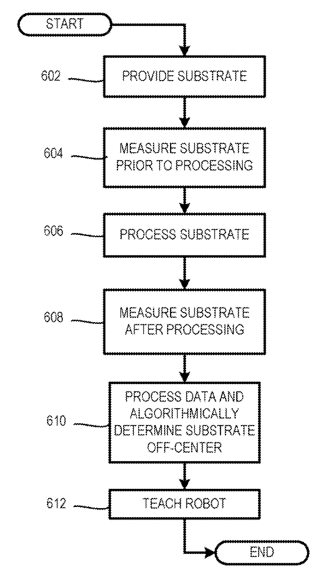
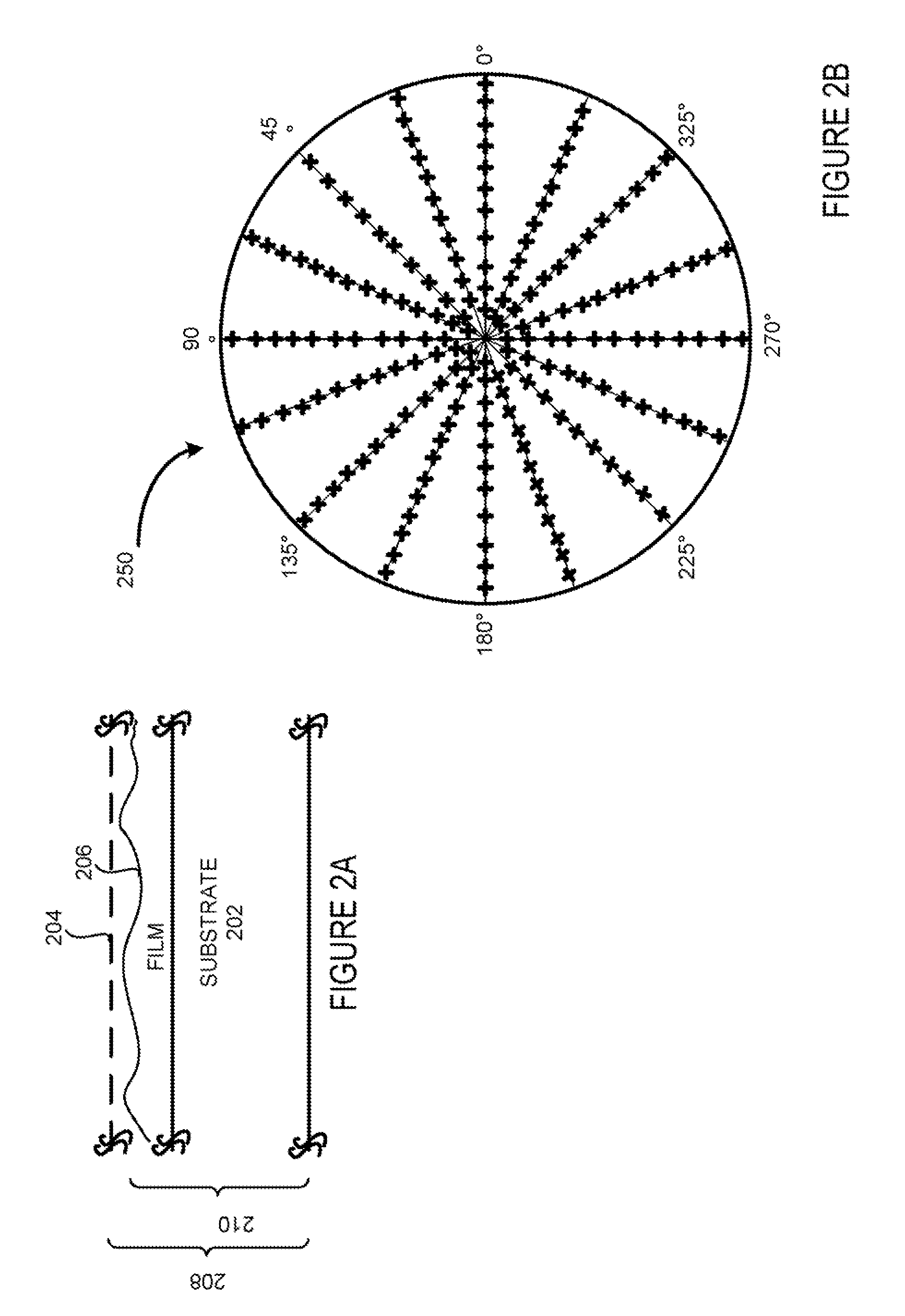
The invention is a method for aligning a substrate to a process center of a support mechanism in a plasma processing chamber. The method involves measuring the thickness of the substrate at different orientations and radial distances from the center of the substrate. A set of process rate values is derived from these thickness values and the duration of the process. An oil-centered plot is created for the first process rate, representing a concentric circle with points on its circumference having the first process rate. A curve-fitting equation is applied to the off-centered plot to determine a set of parameters for offsetting the substrate in relation to the support mechanism. These parameters are then taught to a set of robot arms, which can align another substrate with the process center of the support mechanism. The technical effect of this invention is to improve the accuracy and efficiency of substrate alignment in plasma processing chambers, resulting in higher quality and yield of processed substrates.

Problems solved by technology

Although aligning to a hardware center (e.g., center of the substrate chuck) may be performed with some precision, alignment to the hardware center may not always equate to an alignment to the process center.
As a result, basing alignment on the hardware center alone may cause misalignment during substrate processing.

Method used


Image

  • Offset correction techniques for positioning substrates within a processing chamber
  • Offset correction techniques for positioning substrates within a processing chamber
  • Offset correction techniques for positioning substrates within a processing chamber

Examples


Embodiment Construction

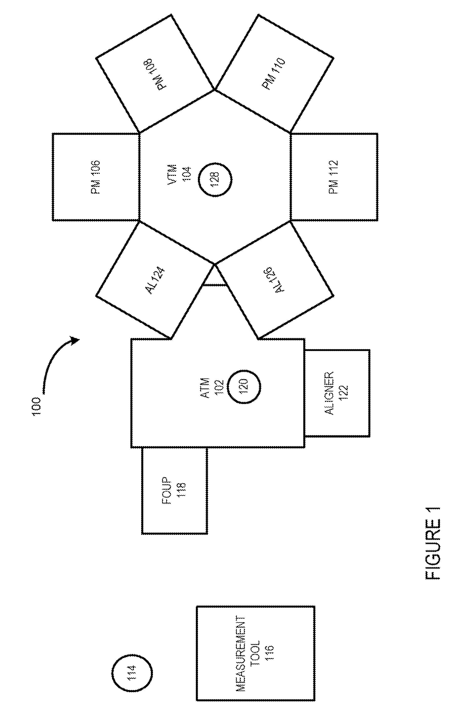
[0036]The present invention will now be described in detail with reference to a few embodiments thereof as illustrated in the accompanying drawings. In the following description, numerous specific details are set forth in order to provide a thorough understanding of the present invention. It will be apparent, however, to one skilled in the art, that the present invention may be practiced without some or all of these specific details. In other instances, well known process steps and / or structures have not been described in detail in order to not unnecessarily obscure the present invention.

[0037]Various embodiments are described hereinbelow, including methods and techniques. It should be kept in mind that the invention might also cover articles of manufacture that includes a computer readable medium on which computer-readable instructions for earning out embodiments of the inventive technique are stored. The computer readable medium may include, for example, semiconductor, magnetic, o...


PUM


Abstract

A method for aligning a substrate to a process center of a support mechanism is provided. The method includes determining substrate thickness after substrate processing at a plurality of orientations and at a plurality of radial distances from a geometric center of the substrate. The method also includes deriving a set of process rate values from substrate thickness and process duration. The method further includes creating for a process rate an off-centered plot which represents a substantially concentric circle whose points are a circumference of the off-centered plot having substantially the first process rate. The method yet also includes applying a curve-fitting equation to the off-centered plot to determine a set of parameters. The method yet further includes teaching a set of robot arms the set of parameters, thereby enabling the set of robot arms to align another substrate that is supported by the support mechanism with the process center.

Description

CROSS-REFERENCE TO RELATED APPLICATIONS[0001]This application is related to and claims priority under 35 U.S.C. §119(e) to a commonly assigned provisional patent application entitled “Offset Correction Techniques For Positioning Substrates Within a Processing Chamber,” by Chen et al., Attorney Docket Number P1756P / LMRX-P147P1, Application Ser. No. 60 / 976,338, filed on Sep. 28, 2007, which is incorporated by reference herein.[0002]The present invention is related to the following applications, all of which are incorporated herein by reference.[0003]Commonly assigned application entitled “Offset Correction Techniques for Positioning Substrates,” by Chen et al., Attorney Docket Number P1596 / P115, application Ser. No. 11 / 612,355, filed on Dec. 18, 2006; and[0004]Commonly assigned application entitled “Offset Correction Methods and Arrangement for Positioning and Inspecting Substrates,” by Chen et. al., Attorney Docket Number P1597 / P116, application Ser. No. 11 / 612,370, filed on Dec. 18,...

Claims


Application Information

Patent Timeline
Patent Type & Authority Applications(United States)
IPC IPC(8): G06F19/00
CPCH01L21/681H01L21/68G05B19/402H01L21/67259H01L21/67265H01L21/67742H01L21/68707G05B2219/40562G05B2219/37608
Inventor CHEN, JACKBAILEY, III, ANDREW C.MOORING, BENCAIN, STEPHEN J.
Owner LAM RES CORP
Learn More