Eureka AIR delivers breakthrough ideas for toughest innovation challenges, trusted by R&D personnel around the world.

Retrieval catheter

a catheter and catheter technology, applied in the field of catheters, can solve the problems of high risk of endovascular surgery, wire tip being diverted and/or ensnared by the stent, and clinicians being required to perform higher risk procedures to retriev

Active Publication Date: 2009-04-02
WL GORE & ASSOC INC
View PDF57 Cites 20 Cited by
  • Summary
  • Abstract
  • Description
  • Claims
  • Application Information

AI Technical Summary

Benefits of technology

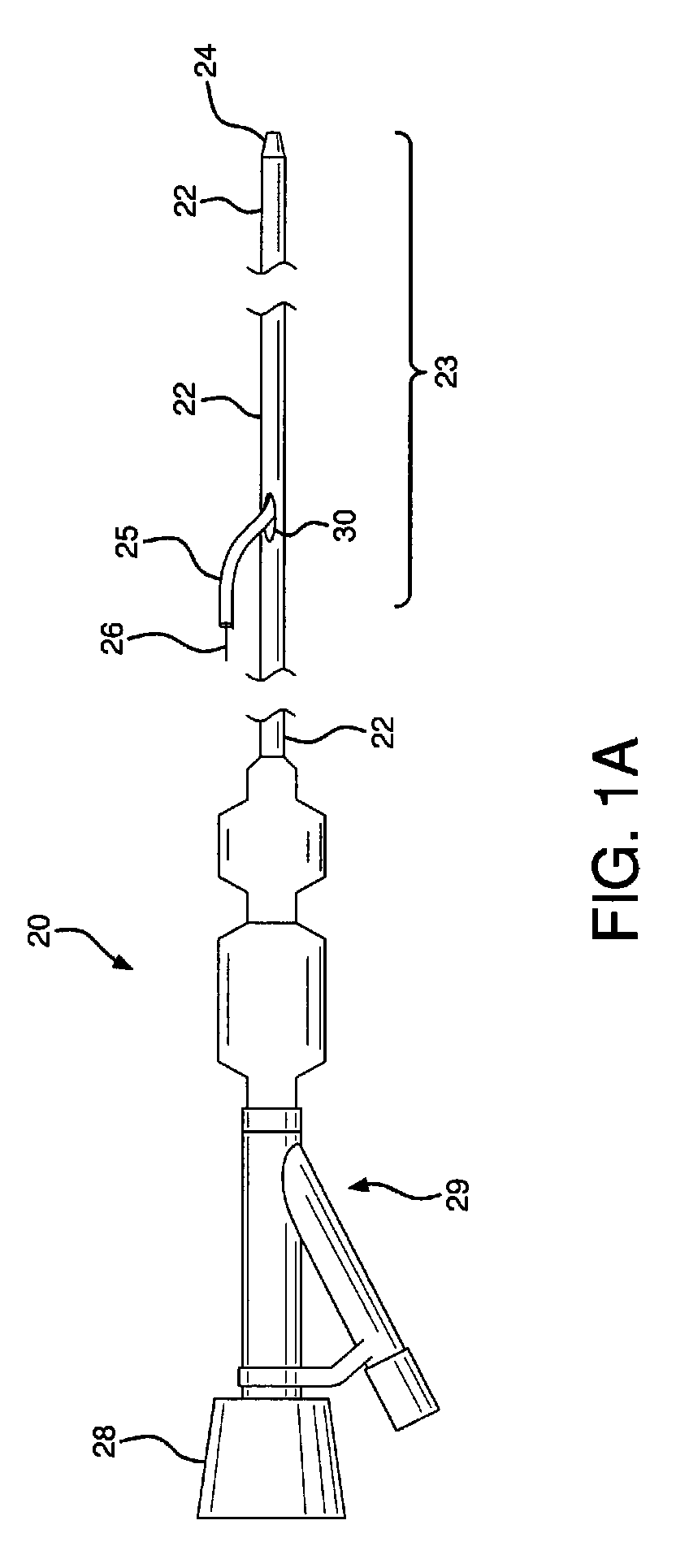
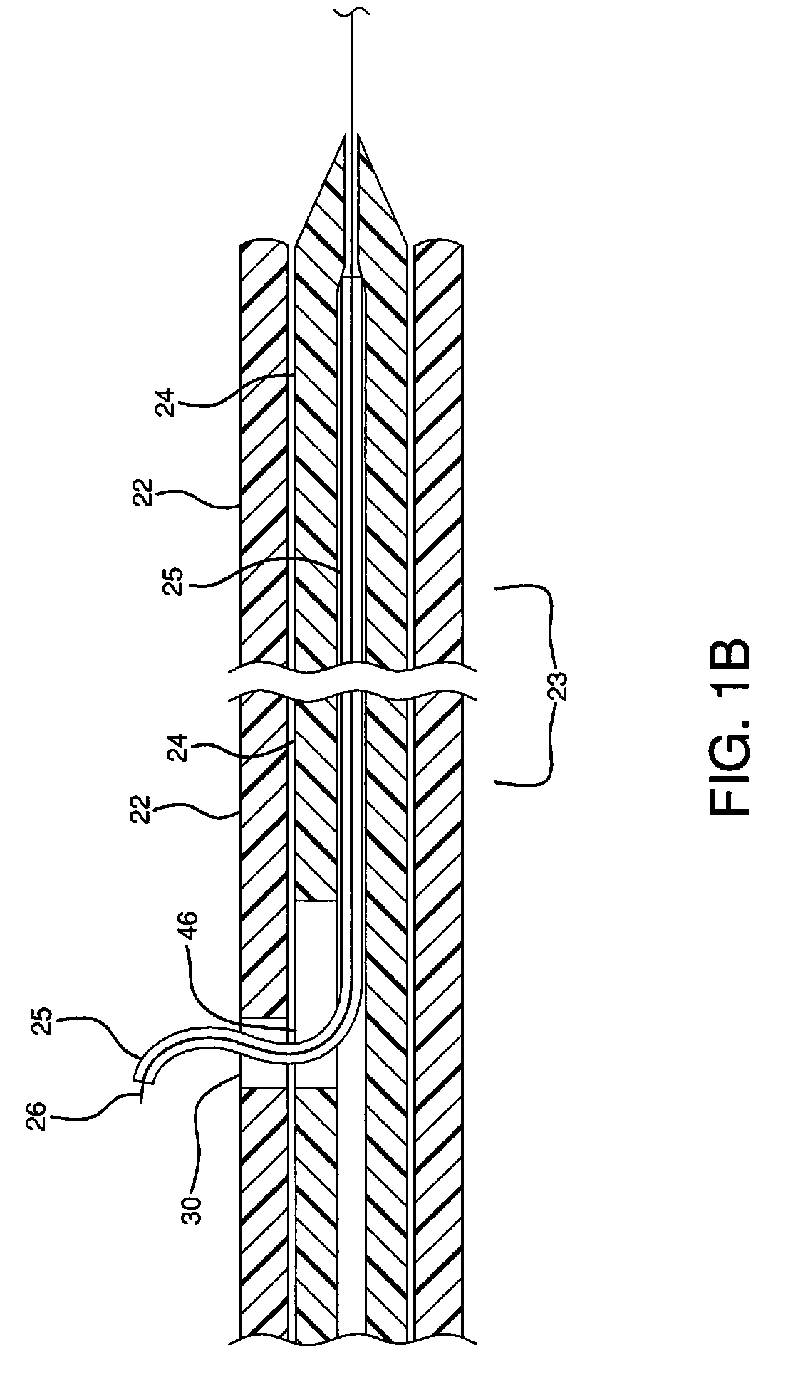
[0006]The retrieval catheter assembly comprises a sheath having a balloon wire or guidewire exchange port through the sidewall of the sheath and a dilator, which is positioned in the sheath lumen. The sheath has a body with relatively stiff proximal and distal sections and with a flexible middle section, which aids in the operation of the device. The dilator is adapted to slide axially relative to the sheath between an extended position and a retracted position while a balloon wire or guidewire extends through the exchange port. When the dilator is withdrawn in a proximal direction into the sheath, it provides a space within the lumen of the distal end of the sheath to accommodate a filter or other device retrieved by the wire.

Problems solved by technology

Distal embolization of friable debris from within the diseased conduit remains a risk of endovascular surgery, potentially involving complications such as myocardial infarction and ischemia.
When feeding a guidewire through the lumen of a stent, there is a possibility that the tip of the wire will become diverted and / or ensnared by the stent.
If a balloon wire or embolic filter becomes caught in the patient's vasculature or is otherwise prevented from removal by a stent, such as the device becoming entrapped within the struts of a stent, then the clinician is typically required to perform higher risk procedures to retrieve them.
The former increases the risk of the device becoming detached from its guidewire or catheter, whereas the latter exposes the patient to the increased risks of open surgical extraction.

Method used


Image

  • Retrieval catheter
  • Retrieval catheter
  • Retrieval catheter

Examples


examples

[0046]To construct a sheath, a 1.24 mm PTFE coated mandrel was loaded with a 1.29 mm inner diameter etched PTFE liner (1.29 mm inner diameter.×0.02 mm thick wall) and secured. A braided sleeving (0.25 mm×0.76 mm stainless steel flat wire, 2 over 2 under, 50 ppi) was loaded and secured at the proximal end of mandrel. The braid was stretched to the distal end of the mandrel and carefully trimmed to length with scissors so that the ends of the wires were uniform. Trimming of the braid length may be achieved with any suitable cutting or trimming tool. A marker band (platinum / iridium, 1 mm width minimum, inner diameter 14.7 mm, 0.25 mm minimum thickness) was slid onto the assembly from the proximal end of the loaded mandrel to the distal end. The marker band was carefully brought up to the end of the braid so that the marker band covered the end of the braid and so that no ends of wires were showing at the marker band. The location of the marker band should be from about 5.08 cm to 6.35 ...


PUM


Abstract

A retrieval catheter operable by a single clinician that will neither displace a deployed stent nor cause undue trauma to the vascular lumen or lesion. The retrieval catheter may be sized to accommodate both a guidewire and a balloon wire. The retrieval catheter is easy to navigate through tortuous passageways and will cross a previously deployed stent or stent-graft easily with minimal risk of snagging on the deployed stent or stent graft. The sheath and dilator are adapted to allow a guidewire or balloon wire to pass through the walls of both and to allow the sheath and dilator to move axially with respect to each other.

Description

FIELD OF THE INVENTION[0001]The present invention relates to catheters used for retrieving, positioning, or repositioning endoluminal devices located distal or adjacent to a stent or other previously implanted device.BACKGROUND OF THE INVENTION[0002]The field of endovascular surgery is rapidly becoming an alternative to more traditional surgeries such as carotid endarterectomy, coronary artery bypass grafting, aortic aneurysm repair, and vascular grafting. Percutaneous intervention is becoming the primary means for revascularization in many such procedures. Distal embolization of friable debris from within the diseased conduit remains a risk of endovascular surgery, potentially involving complications such as myocardial infarction and ischemia. Devices such as balloon catheters and embolic filters have been used to control and remove embolic debris dislodged from arterial walls during endovascular procedures, distal to an interventional procedure site. Percutaneous introduction of t...

Claims


Application Information

Patent Timeline
IPC IPC(8): A61M29/00A61F2/95A61F2/954
CPCA61B2017/22039A61F2/013A61F2230/0006A61F2002/9528A61F2002/9534A61F2002/011A61F2/011A61M2025/0183A61M2025/018A61F2/958
Inventor PARODI, JUAN C.CHEER, JOHNCULLY, EDWARD H.VONESH, MICHAEL J.YOUNG, JEREMY P.
Owner WL GORE & ASSOC INC
Why Eureka
Eureka Blog
Learn More