
Fast Overdriving Method of LCD Panel

a technology of lcd panel and lcd panel, which is applied in the direction of instruments, static indicating devices, etc., can solve the problems of deteriorating display quality of lcd, display luminance cannot reach the target luminance, and conventional lcds cannot display desirable colors and luminances, etc., to achieve the effect of reducing rc loading, reducing aperture ratio, and small size of thin film transistors

Inactive Publication Date: 2009-04-02
KUSN INFOVISION OPTOELECTRONICS
View PDF6 Cites 15 Cited by
  • Summary
  • Abstract
  • Description
  • Claims
  • Application Information

AI Technical Summary

Benefits of technology

[0013]According to embodiments of the invention, the voltage change between the end of a previous frame and the beginning of a current frame can be reduced, thereby decreasing the RC loading so that the size of thin film transistors can be small and the aperture ratio is larger, reducing the Motion Picture Response Time (MPRT) and realizing pre-charge function of pixels without additional devices. In addition, a simpler lookup table for overdrive data can be generated by using black data as input and thus saving storage space. Furthermore, the power consumption for driving the liquid crystal display panel can be further decreased by charging all the black data to the pixels of a corresponding region simultaneously.

Problems solved by technology

In some cases, conventional LCDs cannot display a desirable color and luminance.
When displaying moving images, the display luminance cannot reach a target luminance corresponding to the changed level of video data because of a long response time.
Consequently, a phenomenon of motion illegibility occurs in the moving images and the display quality of the LCD deteriorates due to the decrease of contrast.
However, there is often a relatively large voltage difference between the source data voltage applied in the previous frame and the OD voltage in the current frame, especially when the pixel driving polarity of the current frame is the opposite to that of the previous frame, which is very often the case in today's LCDs.
However, a large thin film transistor results in a larger parasitical capacitance and a high RC delay, and then the aperture ratio must be sacrificed to some extent in order to shield the TFT.
Moreover, a typical overdriving technique needs to obtain overdrive data by searching a relatively complex lookup table, and thus needs a memory with large capacity and high manufacturing cost.

Method used


Image

  • Fast Overdriving Method of LCD Panel
  • Fast Overdriving Method of LCD Panel
  • Fast Overdriving Method of LCD Panel

Examples


Embodiment Construction

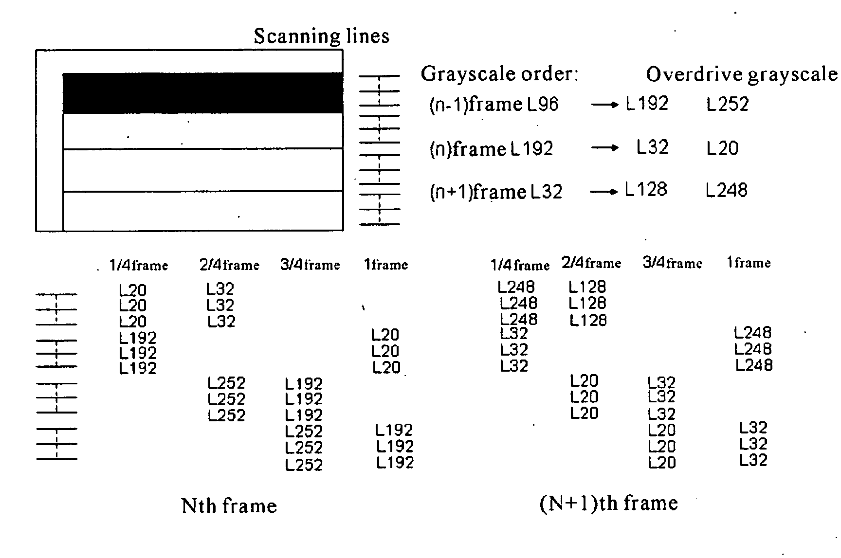
[0025]Embodiments of the invention include an overdriving method in a liquid crystal display panel of a liquid crystal display. Now, an embodiment of the invention will be illustrated with reference to FIGS. 2-7. The objects and features of the invention will be more clarified by the drawings and following description.

[0026]Most of the conventional liquid crystal display panels utilize the Dot Inversion driving method in order to improve the quality of display frames. When the overdrive method of the invention is applied to a Dot Inversion type liquid crystal display panel illustrated in FIG. 2, a driving effect better than the expected driving effect can be achieved (e.g., the power consumption can be further decreased). Therefore, the overdriving method of the invention will be described by taking such Dot Inversion type liquid crystal display panel (hereinafter referred to as “Z-type liquid crystal display panel”) as an example. However, it is noted that the driving method of the...


PUM


Abstract

A driving method for a liquid crystal display (LCD) panel is provided. The method comprises applying corresponding overdriving data for source data to the LCD panel at the beginning of a frame; applying black data to the LCD panel before the end of the frame, wherein the polarities of the applied black data are the same as the pixel electrode driving polarity at the beginning of a next frame; and applying the source data to the LCD panel at a time between the application of the overdriving data and the application of the black data. The driving method of the invention eliminates the need for large TFTs by reducing the voltage change between the end of a previous frame and the beginning of a current frame, and also can perform pre-charging for the pixel electrodes without adding any other device.

Description

FIELD OF THE INVENTION[0001]The invention relates to a liquid crystal display (LCD), and in particular, to a driving method for a LCD panel.BACKGROUND[0002]A LCD generally makes use of characteristics of liquid crystal molecules to display images. LCDs have many advantages such as thinness, light weight, low driving voltage, low power consumption and the like. Therefore, LCDs are widely utilized in various fields.[0003]LCDs display images by adjusting light transmission rate of liquid crystal molecules. An LCD comprises an LCD panel and a driving circuit adapted to drive the LCD panel. The LCD panel includes a plurality of pixels arranged in a matrix form.[0004]The LCD panel comprises an upper substrate, a lower substrate and liquid crystal molecules interposed therebetween. The LCD panel comprises m data lines and n scanning lines, the n scanning lines being substantially vertical to the m data lines so as to define m×n pixels. Each pixel comprises a thin film transistor (TFT) oper...

Claims


Application Information

Patent Timeline
Patent Type & Authority Applications(United States)
IPC IPC(8): G09G3/36
CPCG09G3/3614G09G3/3648G09G2320/0261G09G2310/0251G09G2320/0252G09G2310/0205
Inventor CHUNG, TE-CHENJEN, TEAN-SENZHANG, JUNRUI
Owner KUSN INFOVISION OPTOELECTRONICS
Learn More