
Transmission for vehicles

Inactive Publication Date: 2009-04-02
HONDA MOTOR CO LTD
View PDF4 Cites 18 Cited by
  • Summary
  • Abstract
  • Description
  • Claims
  • Application Information

AI Technical Summary

Benefits of technology

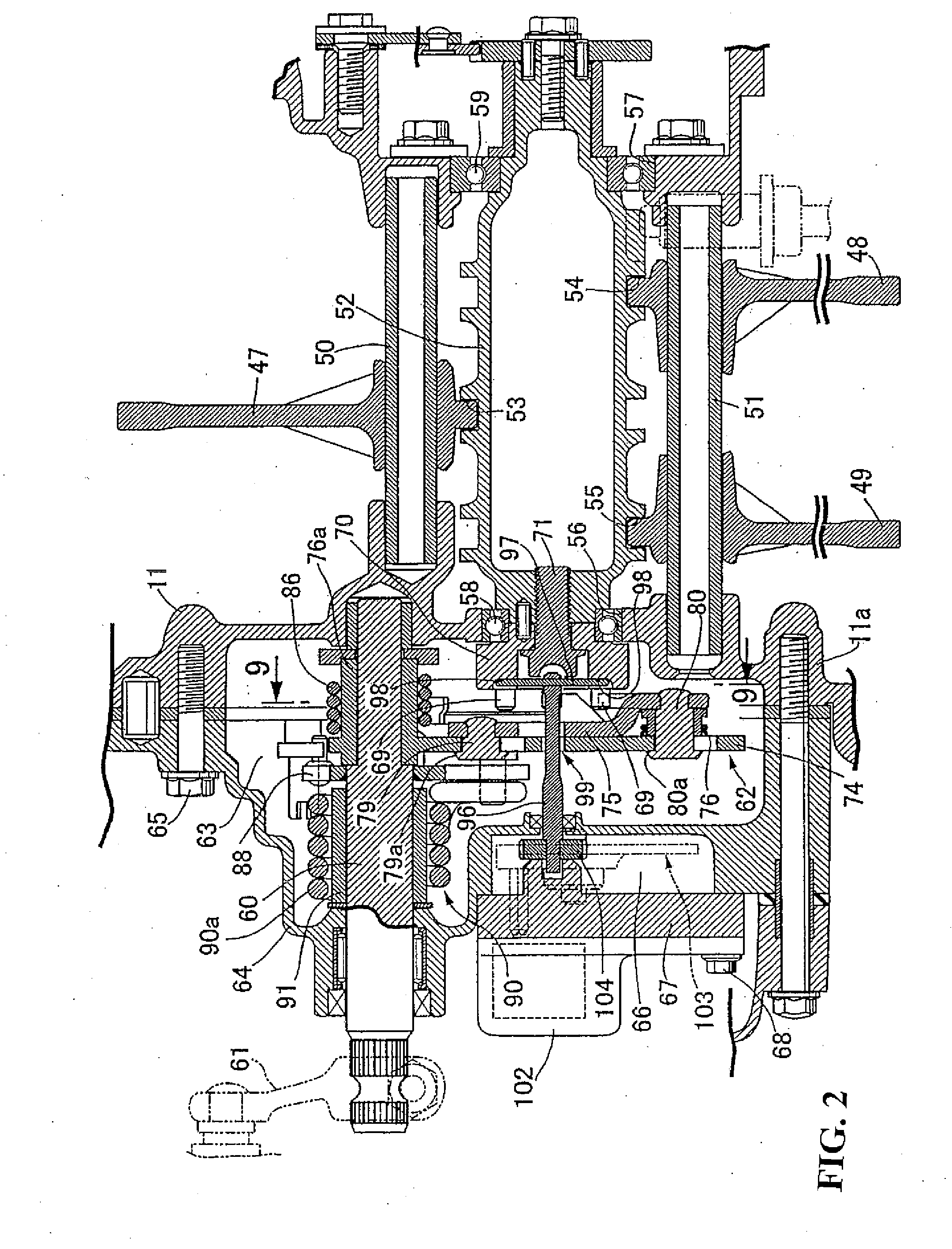
[0018]According to an embodiment of the present invention, the opening angle between the arm member and the turning member is calculated on the basis of the detection value of the drum turning amount detecting means for detecting the turning amount of the shift drum and of the detection value of the turning member turning-amount detection means. In addition, the operating load inputted to the shift spindle can be calculated on the basis of the opening angle. Thus, the shift operational load can be calculated without use of an expensive load sensor.
[0029]According to an embodiment of the present invention, since the shifting position sensor is disposed externally of the engine case and of the shift cover, the thermal influence on the shifting position sensor from the engine can further be reduced. In addition, it is possible to further enhance the maintenance performance of the shifting position sensor.

Problems solved by technology

Further, there is a possibility that a shifting operational load may excessively be applied to component parts such as a shift drum and the like.

Method used


Image

  • Transmission for vehicles
  • Transmission for vehicles
  • Transmission for vehicles

Examples


Embodiment Construction

[0043]One embodiment of the present invention will hereinafter be described with reference to the accompanying drawings.

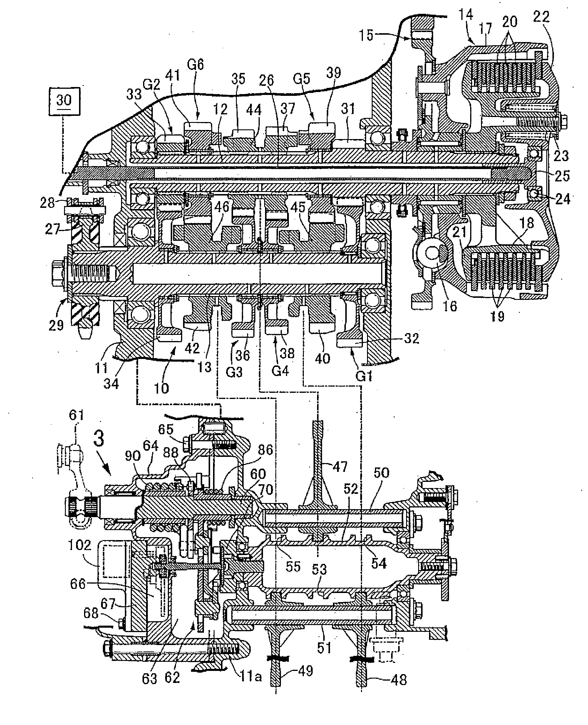
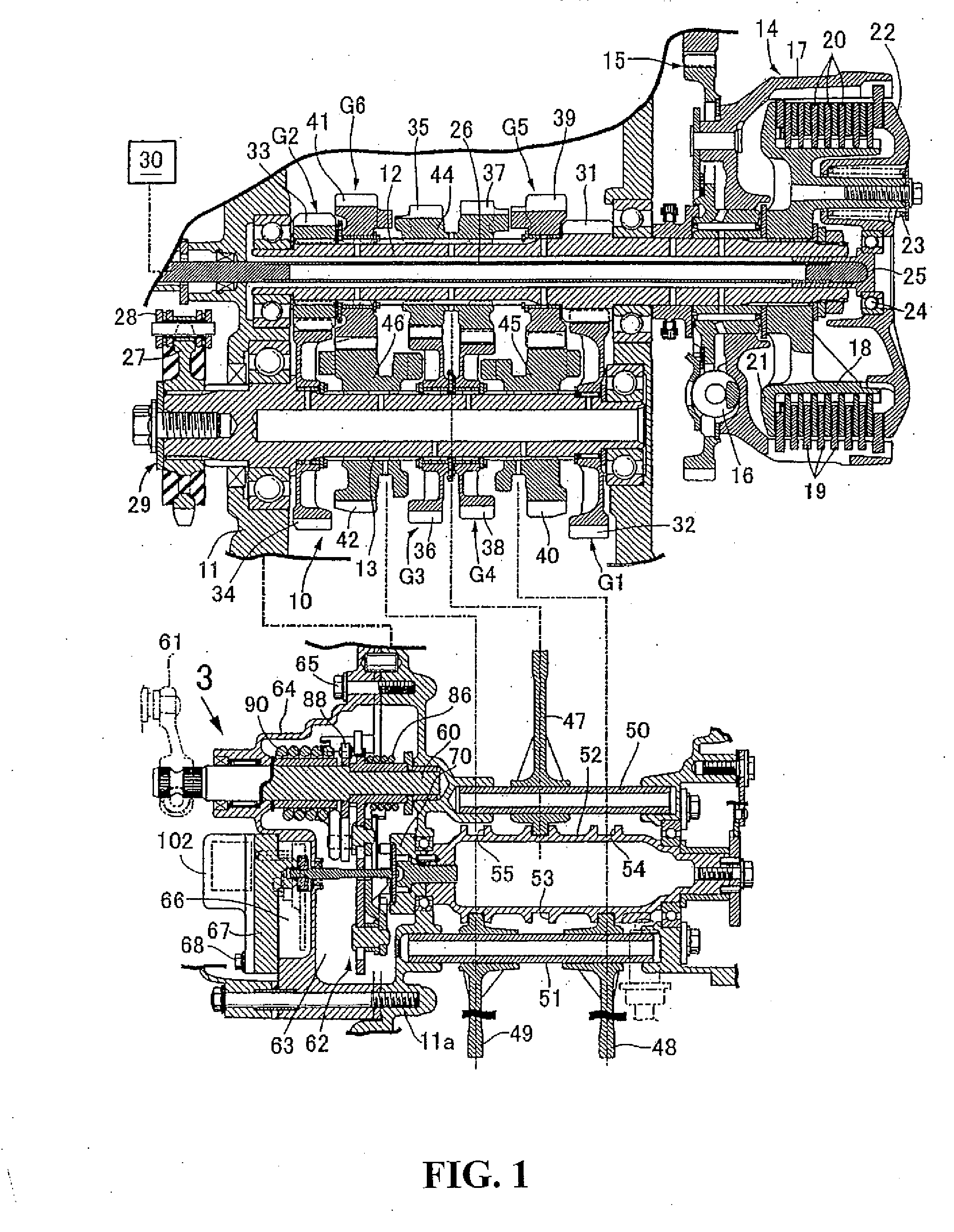
[0044]FIGS. 1 through 11 illustrate one embodiment of the present invention. In FIG. 1, the transmission may be used with a motorcycle and includes a gear shifting mechanism 10 configured such that a plurality of speed steps, e.g., first through sixth speed gear trains G1, G2, G3, G4, G5 and G6 are provided between a main shaft 12 as a speed change input shaft and a counter shaft 13 as a speed change output shaft so as to enable selectable establishment. The main shaft 12 and the counter shaft 13 have respective axes parallel to each other and are rotatably journaled by an engine case 11. The first through sixth speed gear trains G1 through G6 are accommodated in the engine case 11.

[0045]A clutch 14 is provided between a crankshaft (not shown), a power source output shaft, of an engine and one end of the main shaft 12 to switch between connection and disconnection ...


PUM


Abstract

A shift position changing drive member for a transmission includes an arm member capable of turning around the axis of a shift spindle for drivingly turning a shift drum in response to the turning of the shift spindle wherein the shift drum is prevented from coming into a neutral position even if the shifting speed is stopped in midstream. A lost motion spring includes gripping portions gripping a pressing portion from both sides of a coil portion surrounding the shift spindle. An arm member of shift position changing drive member is provided with a pressure-receiving member which is gripped by both gripping portions in such a manner that when the turning member is turned, if, in response to the turning direction, the pressing portion abuts against one of the gripping portions for turning, the other of the gripping portions abuts against the pressure-receiving member.

Description

CROSS-REFERENCE TO RELATED APPLICATIONS[0001]The present application claims priority under 35 USC 119 to Japanese Patent Application No. 2007-256537 filed on Sep. 28, 2007 and Japanese Patent Application No. 2007-256536 filed on Sep. 28, 2007 the entire contents of which are hereby incorporated by reference.BACKGROUND OF THE INVENTION[0002]1. Field of the Invention[0003]The present invention relates to a transmission for a vehicle that includes a gear shifting mechanism provided with a plurality of selectively establishable gear trains for speed steps between a speed change input shaft and a speed change output shaft. A clutch is adapted to switch between connection and disconnection of power transmission between a power source output shaft and the speed change input shaft with a shift drum turnably carried by an engine case so as to selectively establish the gear trains in response to a turning position. A shift spindle is turnably attached to the engine case so as to turn in respo...

Claims


Application Information

Patent Timeline
IPC IPC(8): F16H3/08
CPCF16H59/68F16H63/14Y10T74/19219Y10T74/19279F16H63/18
Inventor HAYAKAWA, KOSHIIWASHITA, KANAUIEDA, YOSHIHISATOMODA, AKIHIKOSAHODA, KATSUMI
Owner HONDA MOTOR CO LTD
Learn More