Eureka AIR delivers breakthrough ideas for toughest innovation challenges, trusted by R&D personnel around the world.

Distributed antenna system using overhead power lines

a technology of overhead power lines and distributed antennas, applied in the field of telecommunications systems, can solve the problems of increasing the cost of increasing the information capacity of served areas or the coverage of unserved areas, and the original flooding approach used by cellular mobile services, etc., and achieve the effect of improving the appreciation of the contribution to the ar

Inactive Publication Date: 2009-03-26
CORRIDOR SYST INC
View PDF7 Cites 678 Cited by
  • Summary
  • Abstract
  • Description
  • Claims
  • Application Information

AI Technical Summary

Benefits of technology

[0031]A final noteworthy, though not final object and advantage of the present invention, is to provide a distributed antenna system that facilitates greater battery life for portable CPE.
[0032]There has thus been broadly outlined the more important features of the invention in order that the detailed description that follows may be better understood, and in order that the present contribution to the art may be better appreciated. Additional objects, advantages and novel features of the invention will be set forth in part in the description as follows, and in part will become apparent to those skilled in the art upon examination of the following. Furthermore, such objects, advantages and features may be learned by practice of the invention, or may be realized and attained by means of the instrumentalities and combinations particularly pointed out in the appended claims.

Problems solved by technology

As capacity and coverage requirements for personal and mobile communications have escalated, the original flooding approach used by cellular mobile service providers, that of attempting total coverage of a relative large area surrounding a centralized cellular base station site, has fallen increasingly short of requirements.
Due to the length of the average radio propagation path and the large amount of associated attenuation in typical rural, suburban or urban environments, the cost of increasing either information capacity of served areas or coverage into unserved areas can be prohibitive.
Additionally, in many locations, the availability of suitable sites is dwindling and new site procurement is becoming more expensive or even unattainable due to local zoning restriction and regulation.
But due to the cost for both equipment and additional back haul, this is an unacceptably expensive solution.
In addition to the hardware and back haul costs already mentioned, a considerable portion of the cost of coverage addition and extension, independent of the type, has been due to the expense of coverage planning and the analysis of local terrain and environment.
For all of these reasons, existing DAS solutions have had limited success.

Method used


Image

  • Distributed antenna system using overhead power lines
  • Distributed antenna system using overhead power lines

Examples


Embodiment Construction

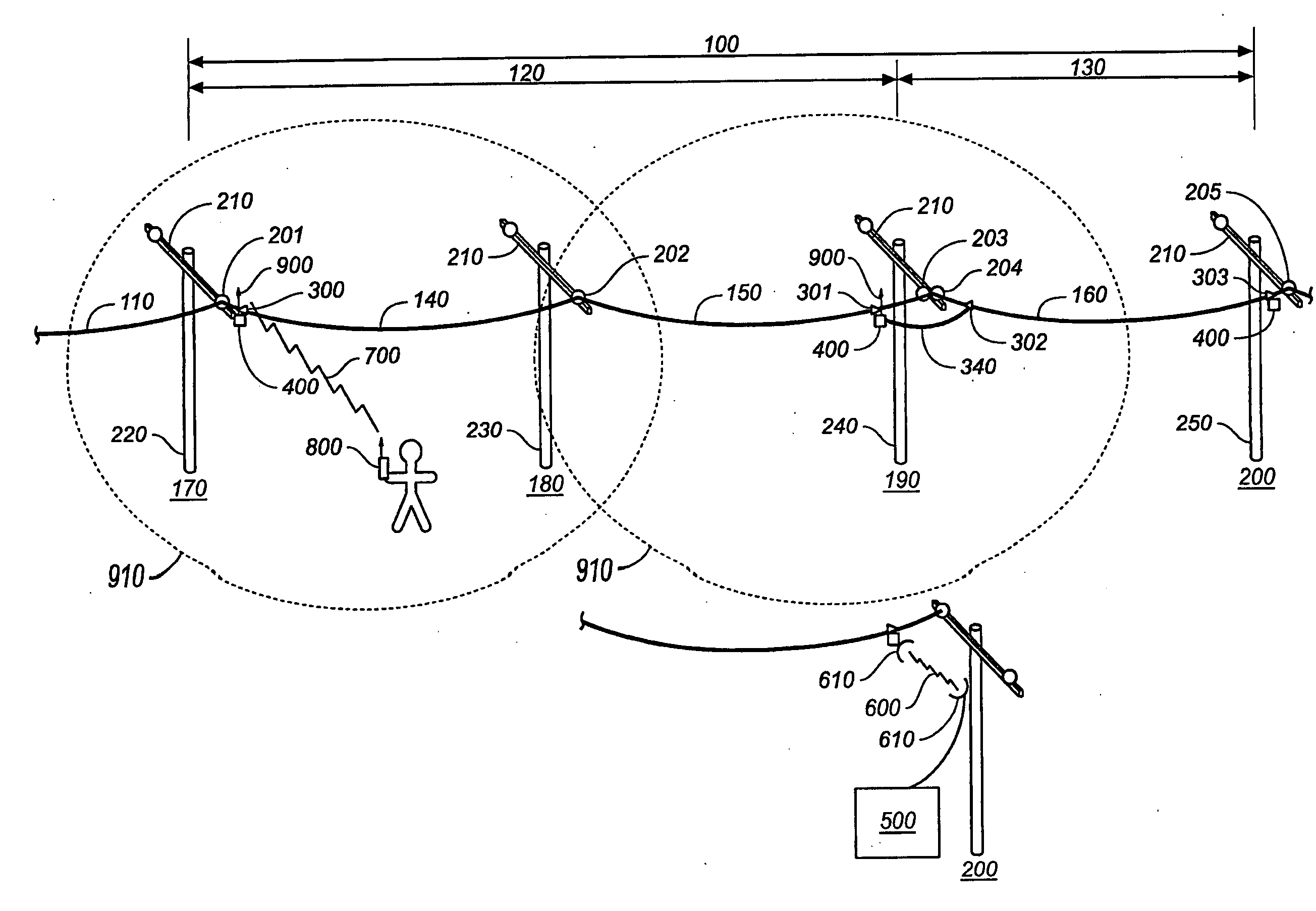
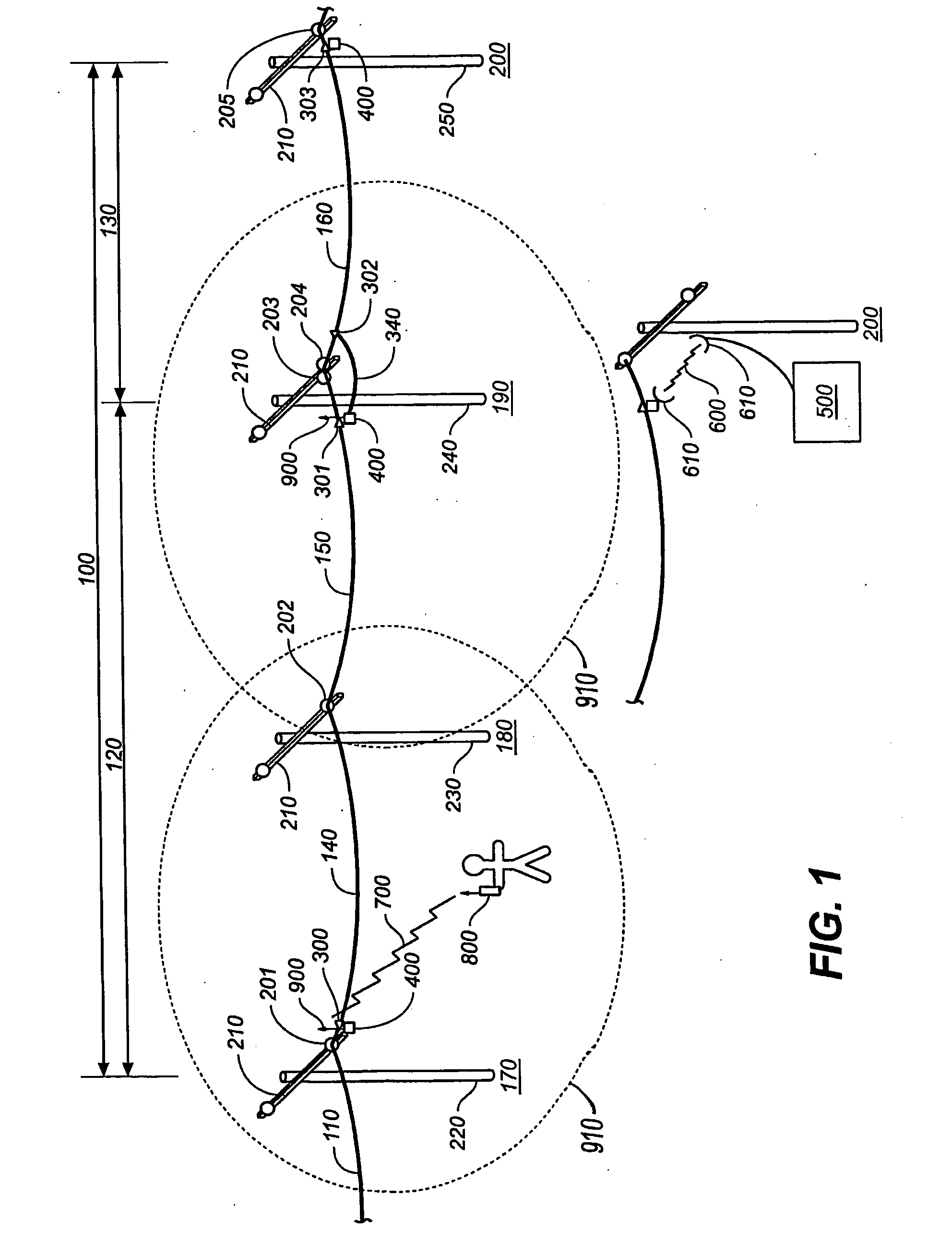
[0036]FIG. 1 is a schematic view illustrating a new and improved distributed antenna system using overhead power lines. The inventive system comprises two functional aspects: transport and distribution. Transport relates to that portion of the system that provides for the transmission and maintenance of system information capacity along the length of the line. Distribution relates to the portion or portions of the system that provide local access at one or more points along the line and at the end points.

[0037]Transport. The transport function of this invention operates by dividing a length of overhead power line 100, into one or more segments, 120, 130. Each segment includes one or more spans 140, 150, 160 of power line, having supporting structures 170, 180, 190, 200 at their respective ends. These support structures typically comprise insulators 201, 202, 203, 204, 205, cross arms 210, and poles 220, 230, 240, 250, or other physically fixed structures to support the weight of the...


PUM


Abstract

A distributed antenna system having a transport portion including at least one overhead power line for transmitting system information along its length, and a distribution portion including at least one local access point disposed along the length of the power line for providing local access to information transported by the transport portion.

Description

BACKGROUND OF THE INVENTION[0001]1. Technical Field[0002]The present invention relates generally to telecommunications systems, and more particularly to a novel method for utilizing overhead transmission lines for both the transport and distribution of information.[0003]2. Background Art[0004]As capacity and coverage requirements for personal and mobile communications have escalated, the original flooding approach used by cellular mobile service providers, that of attempting total coverage of a relative large area surrounding a centralized cellular base station site, has fallen increasingly short of requirements. Although the quantity of installed cell sites has steadily increased, both in the US and worldwide, demand has increased faster. Due to the length of the average radio propagation path and the large amount of associated attenuation in typical rural, suburban or urban environments, the cost of increasing either information capacity of served areas or coverage into unserved a...

Claims


Application Information

Patent Timeline
Patent Type & Authority Applications(United States)
IPC IPC(8): H01Q1/00H04H1/00H04H20/84
CPCH04B3/56H04H20/84H04B2203/5483H04B2203/5441
Inventor ELMORE, GLENN E.
Owner CORRIDOR SYST INC
Why Eureka
Eureka Blog
Learn More