Electric Motor, Drive System Employing Multiple Electric Motors, and Method for Controlling the Same
a technology of electric motors and motors, applied in the direction of motor/generator/converter stoppers, electronic commutators, dynamo-electric converter control, etc., can solve the problem of inability to achieve accurate motor control, inability to satisfactorily carry out motor control, and inability to use satisfactory technology for achieving accurate motor control. , to achieve the effect of simplifying the transmission of shared commands
- Summary
- Abstract
- Description
- Claims
- Application Information
AI Technical Summary
Benefits of technology
Problems solved by technology
Method used
Image
Examples
embodiment 1
1. Embodiment 1
1-A. Configuration of Electric Motor
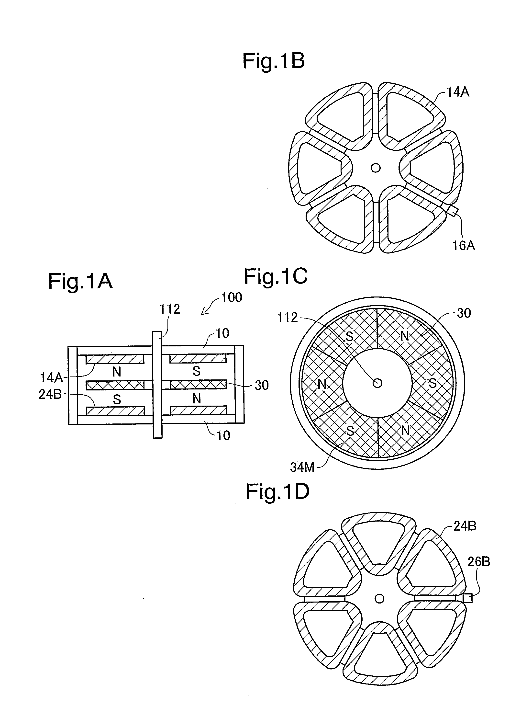
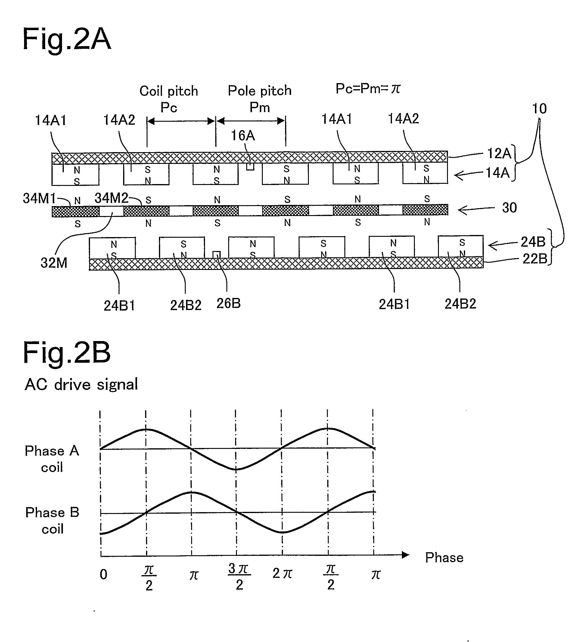
[0077]FIG. 1A is a sectional view showing the configuration of the motor unit of an electric motor in one embodiment of the present invention. This motor unit 100 has a stator unit 10 and a rotor unit 30, each of generally disk shape. The rotor unit 30 has a magnet array 34M composed of a number of magnets, and is affixed to a rotating shaft 112. The direction of magnetization of the magnet array 34M is the vertical direction. The stator unit 10 has a Phase A coil array 14A positioned above the rotor unit 30, and a Phase B coil array 24B positioned below the rotor unit 30.
[0078]FIGS. 1B to 1D depict, in detached form, the first coil array 14A of the stator unit 10, the rotor unit 30, and the second coil array 24B of the stator unit 10, respectively. In this example, the Phase A coil array 14A and the Phase B coil array 24B each have six coils; likewise, the magnet array 34M has six magnets. However, it is possible to set the number ...
embodiment 2
2. Embodiment 2
[0152]FIG. 27 is a block diagram depicting the configuration of the drive system in Embodiment 2. This drive system is furnished with multiple electric motors 10b. Here, the number of motors is denoted by M where M is an integer equal to 2 or greater. The multiple electric motors 100b are connected to a drive power supply 1200 via a power line PL, and also connected to a system controller 1300 via a control line CL. The power line PL and the control line CL are shared by the multiple electric motors 100b. Alternatively, power lines PL may be individually connected to the motors.
[0153]Each of the electric motors 100b is assigned a unique ID code (identification code) identifying it from the other electric motors. As will be discussed later, the system controller 1300 uses this ID code to send commands to individual electric motors 100b via the control line CL.
[0154]FIG. 28 is a block diagram depicting the configuration of the drive control circuit provided in each indi...
modification examples
3. Modification Examples
[0187]The present invention is not limited to the embodiments described hereinabove, and may be reduced to practice in various other ways without departing from the spirit thereof. Modifications such as the following would be possible, for example.
PUM
 Abstract
Description
Claims
Application Information
 - R&D
- Intellectual Property
- Life Sciences
- Materials
- Tech Scout
- Unparalleled Data Quality
- Higher Quality Content
- 60% Fewer Hallucinations
Browse by: Latest US Patents, China's latest patents, Technical Efficacy Thesaurus, Application Domain, Technology Topic, Popular Technical Reports.
© 2025 PatSnap. All rights reserved.Legal|Privacy policy|Modern Slavery Act Transparency Statement|Sitemap|About US| Contact US: help@patsnap.com


