
Toroidal ring manifold for secondary fuel nozzle of a dln gas turbine

a gas turbine and secondary fuel technology, applied in the direction of machines/engines, mechanical equipment, lighting and heating apparatus, etc., can solve the problems of incomplete effective mixing of fuel and air, elevated emissions of gas turbines, and inability to properly mix fuel and air, so as to promote the effect of reducing emissions and improving combustion dynamics

Inactive Publication Date: 2009-03-26
GENERAL ELECTRIC CO
View PDF9 Cites 27 Cited by
  • Summary
  • Abstract
  • Description
  • Claims
  • Application Information

AI Technical Summary

Benefits of technology

[0014]The present invention relates to a toroidal ring manifold for effectively dispersing premixing fuel with air in the secondary nozzle of a combustor for a DLN gas turbine, thereby providing stable combustion with low nitrogen oxide (NOx) emissions.

Problems solved by technology

However, the effective mixing of fuel and air is not complete.
However, elevated emissions from a gas turbine is the result of insufficient mixing of air and fuel prior to burning in the combustion chamber.
The existing peg design, described above, is not able to mix fuel and air properly to obtain the requisite degree of mixing for low emissions.
Attempts to change the location of holes in the pegs have not been able to achieve satisfactory fuel and air mixing.
However, the rectangular-shaped annulus limits the angles of the apertures may make with respect to the direction of the airstream.
However the annular manifold has limitations on mixing, stemming from the limited flow angles that may be created within respect to the airflow, and particularly with respect to the radial distribution of fuel into the airstream.

Method used


Image

  • Toroidal ring manifold for secondary fuel nozzle of a dln gas turbine
  • Toroidal ring manifold for secondary fuel nozzle of a dln gas turbine
  • Toroidal ring manifold for secondary fuel nozzle of a dln gas turbine

Examples


Embodiment Construction

[0037]The following embodiments of the present invention have many advantages, including effectively dispersing premixing fuel with air in the secondary nozzle of a combustor for a Dry Low NOx (DLN) gas turbine, thereby providing stable combustion with low nitrogen oxide (NOx) emissions.

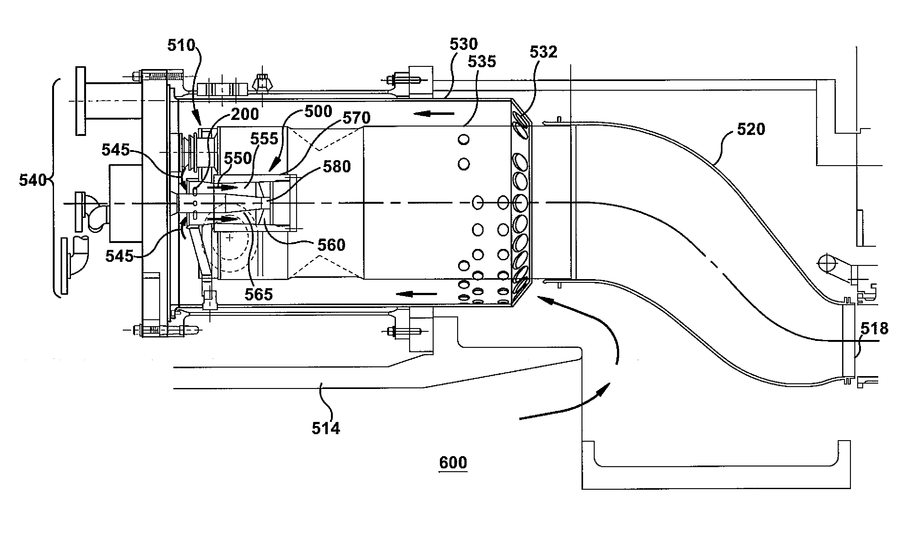
[0038]According to one aspect of the present invention a toroidal ring manifold is provided to disperse fuel into the premixing volume between a secondary nozzle body and the finer. FIG. 5A illustrates a cross-section of a toroidal shell. A toroidal ring manifold 200 may comprise a generally toroidal-shaped shell 210, with a circular ring cross section 215. The toroidal-shaped shell 210 is centered on a poloidal axis 220. When the toroidal ring manifold 200 is united with a nozzle body 400 (partially shown) as part of a secondary fuel assembly, the poloidal axis may be coincident with a longitudinal axis 305 of the nozzle body 400. A toroidal axis 225 runs through the center 230 of circular ring cros...


PUM


Abstract

A toroidal ring manifold for effectively dispersing premixing fuel with air in the secondary fuel nozzle of a combustor for a Dry Low NOx (DLN) gas turbine, thereby providing stable combustion with low nitrogen oxide (NOx) emissions. The toroidal ring manifold is centered around a centerbody hub of a secondary fuel nozzle assembly in a premixing volume between the nozzle centerbody hub body and a centerbody cap. The ring manifold receives fuel from the nozzle body and dispenses premix fuel from a plurality of rows of individual holes on its downstream surface into an axial airstream. The number and location of the rows, the number, size and spacing of holes in each row, and the radial position of the toroidal ring manifold within the premixing volume are optimized to promote premixing.

Description

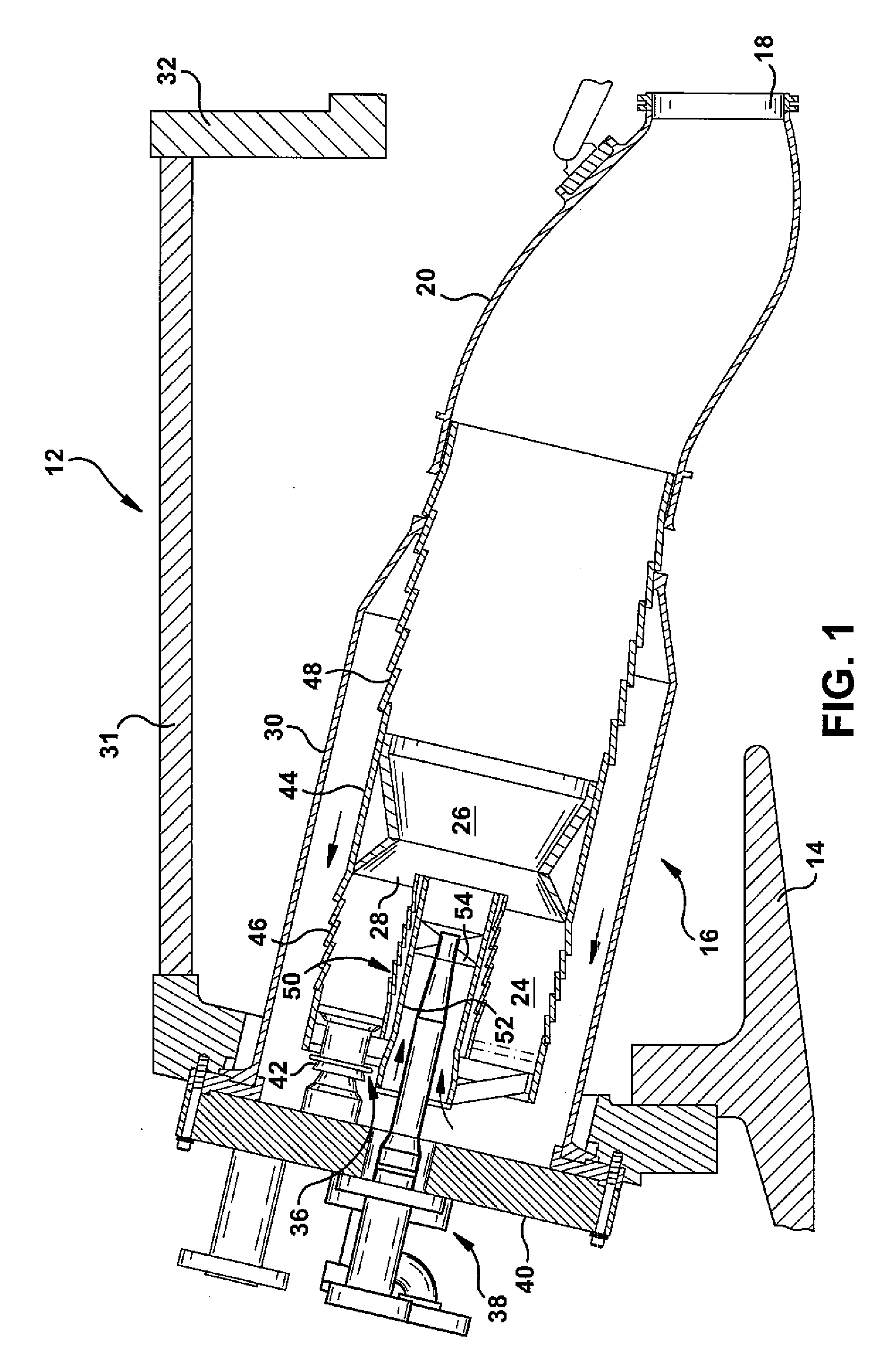
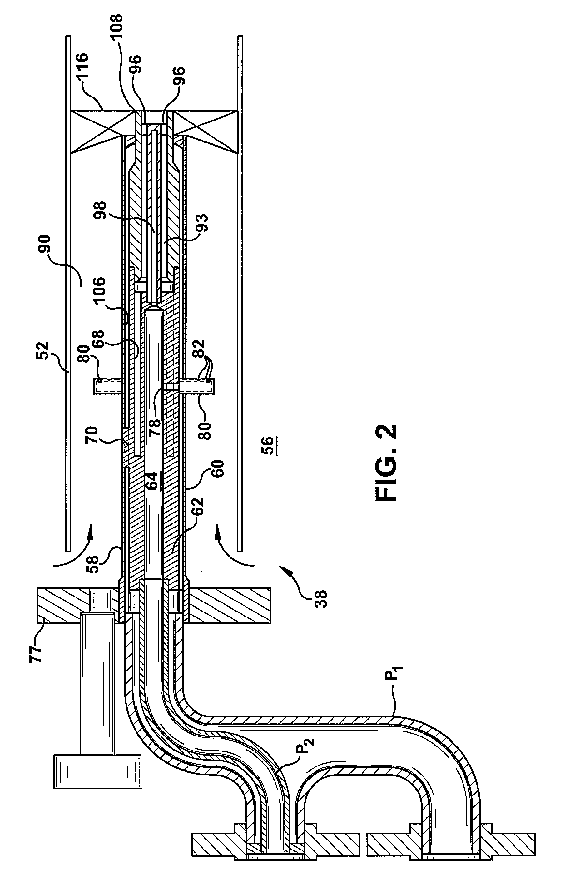
BACKGROUND OF THE INVENTION[0001]The invention relates generally to a secondary fuel nozzle for a gas turbine combustor and more specifically to a toroidal ring manifold for fuel premixing in the secondary fuel nozzle of a Dry Low NOx (DLN) gas turbine.[0002]FIG. 1 illustrates a prior art combustor for a gas turbine 12, which includes a compressor 14 (partially shown), a plurality of combustors 16 (one shown for convenience and clarity), and a turbine represented by a single blade 18. Although not specifically shown, the turbine 16 is drivingly connected to the compressor 14 along a common axis. The compressor 14 pressurizes inlet air, which is then reverse flowed to the combustor 14 where it is used to cool the combustor 16 and to provide air to the combustion process. Although only one combustor 14 is shown, the gas turbine 10 includes a plurality of combustors 16 located about the periphery thereof. A transition duct 20 connects the outlet end of each combustor 16 with the inlet ...

Claims


Application Information

Patent Timeline
Patent Type & Authority Applications(United States)
IPC IPC(8): F23R3/28
CPCF02C7/222F23R3/286F05D2250/70F23R2900/03343F23R3/343
Inventor SINGH, ARJUN
Owner GENERAL ELECTRIC CO
Learn More