Vehicle interior illumination system
- Summary
- Abstract
- Description
- Claims
- Application Information
AI Technical Summary
Benefits of technology
Problems solved by technology
Method used
Image
Examples
embodiment 1
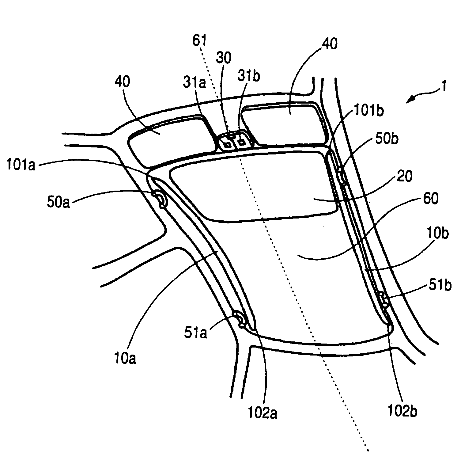
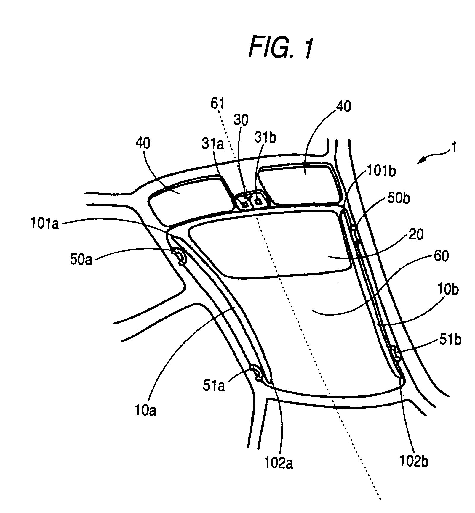
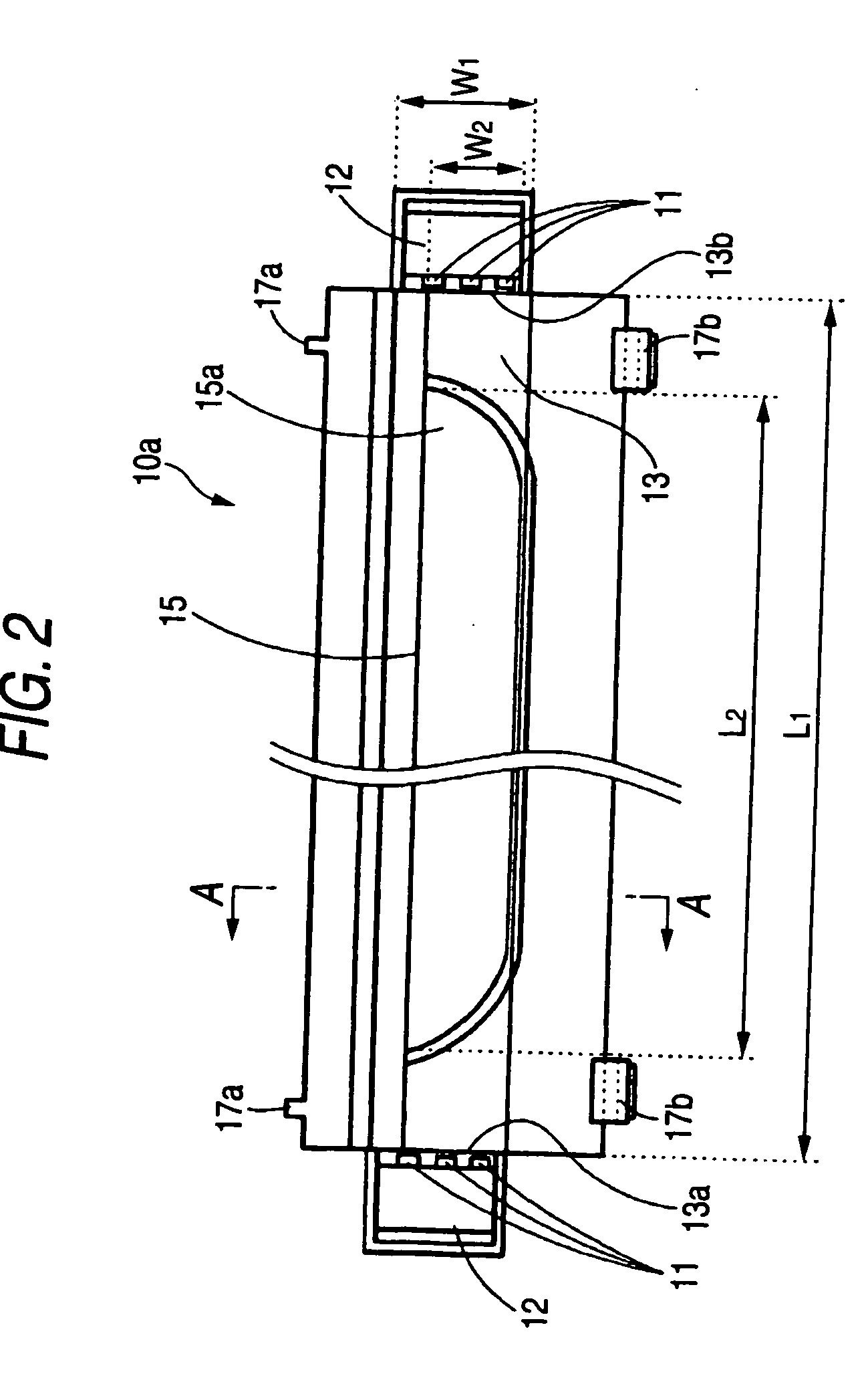
[0049]FIG. 1 is a perspective view of a vehicle passenger compartment ceiling 60 which includes a vehicle illumination system 1 which is an embodiment of the invention. Provided on the passenger compartment ceiling are a first linear illumination unit 10a, a second linear illumination unit 10b, a sun roof 20, an overhead console 30, sun visors 40, and assist grips 50a, 50b, 51a, 51b. The first linear illumination unit 10a is provided further inwards towards the center of a vehicle passenger compartment ceiling 60 than the assist grips 50a, 51a provided on a driver's seat side of the vehicle passenger compartment ceiling 60 and in such a manner as to follow an outer periphery of a driver's side edge of the vehicle passenger compartment ceiling 60. A front end 101a of the first linear illumination unit 10a is positioned further forwards than the driver's seat side assist grip 50a, while a rear end 102a of the first linear illumination unit 10a is positioned further rearwards than the ...
embodiment 2
[0056]FIG. 4 shows a perspective view of a ceiling 460 of a passenger compartment of a vehicle which includes a vehicle illumination system 400 of another embodiment or Embodiment 2 of the invention, and FIG. 5 shows an enlarged sectional view taken along the line B-B in FIG. 4. Like reference numerals will be imparted to like members to the members described in Embodiment 1, and the description thereof will be omitted. Provided on a passenger compartment ceiling are a first linear illumination unit 410a, a second linear illumination unit 410b, a sun roof 20, an overhead console 30, sun visors 40, and assist grips 50a, 50b, 51a, 51b. The first linear illumination unit 410a is provided at a driver's seat side edge portion of a vehicle passenger compartment ceiling 460 in such a manner as to lie further inwards towards the center of the vehicle passenger compartment ceiling 460 than the assist grips 50a, 51a provided on a driver's seat side of the vehicle passenger compartment ceiling...
embodiment 3
[0059]In the embodiment 1, the casing 17 is provided on the rear surface of the light guiding plate 13, However, in this embodiment 3, as shown in FIG. 7, a reflection layer 13c is provided on a rear surface (an opposite surface to the vehicle passenger compartment side surface) of the light guiding plate 13, the casing 17 is provided on the reflection layer 13c (the opposite surface to the vehicle passenger compartment side surface) of the light guiding plate 13 via the reflection sheet 4 and a cushion piece 19. The bezel 16 is fixed to the casing 17 with screws 18, whereby the designed lens 15, the light guiding plate 13, the reflection sheet 14 and the cushion piece 19 are held between the casing 17 and the bezel 16 in that order. Here, like reference numerals is imparted to like members to the members described in Embodiment 1, and the description thereof will be omitted.
[0060]In embodiment 1, by the switches 31a, 31b being turned on, or in association with a vehicle door being ...
PUM
 Abstract
Description
Claims
Application Information
 - R&D
- Intellectual Property
- Life Sciences
- Materials
- Tech Scout
- Unparalleled Data Quality
- Higher Quality Content
- 60% Fewer Hallucinations
Browse by: Latest US Patents, China's latest patents, Technical Efficacy Thesaurus, Application Domain, Technology Topic, Popular Technical Reports.
© 2025 PatSnap. All rights reserved.Legal|Privacy policy|Modern Slavery Act Transparency Statement|Sitemap|About US| Contact US: help@patsnap.com


