
Device and method for large-screen projection of digital images onto a projection screen

a technology of projection screen and digital image, which is applied in the direction of projectors, instruments, optics, etc., can solve the problems of reducing the quality of three-dimensional image representation for the viewer, and likewise having a negative effect on the quality of the 3d digital image projected, and achieves an increase in image quality

Inactive Publication Date: 2009-03-19
KINOTON
View PDF2 Cites 8 Cited by
  • Summary
  • Abstract
  • Description
  • Claims
  • Application Information

AI Technical Summary

Benefits of technology

[0006]The task on which the present invention is therefore based is that of providing a further development of a large-screen projection device having a polarizing mechanism as well as a corresponding method for the large-screen projection of digital images onto a projection screen using a device of the type cited at the outset in such a way so as to avoid the problems and disadvantage known from the prior art and discussed above and, in particular, which achieves an appreciable increase in image quality.
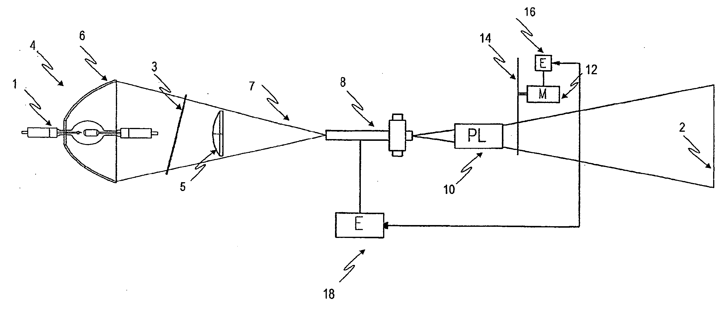
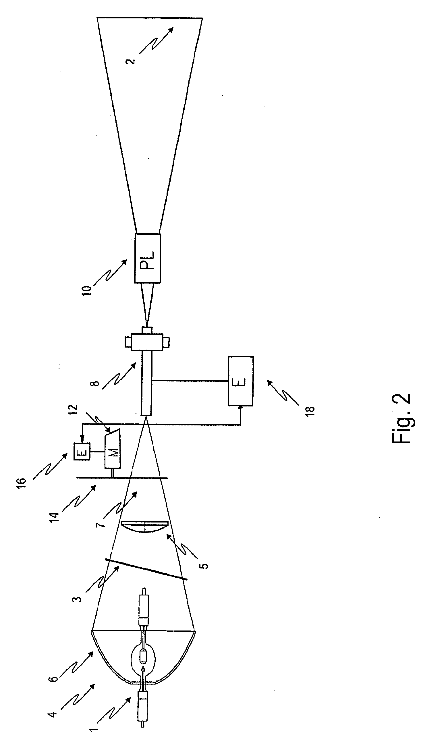
[0011]An essential point of the invention lies in the fact that the synchronized control of the image generator and the 3D-sectored polarization wheel according to a given image sequencing from the image generator enables a synchronized and incremental rotation of a 3D-sectored polarization wheel such that each individual image generated by the image generator, each generated successively for the left and the right eye of the viewer, is precisely projected through the polarizing sector associated with its polarization. The projection of the desired images through the beam of light thus occurs in a manner that the respective half-image generation is synchronized to the alternating polarizations of the 3D-sectored polarization wheel. This thereby effectively prevents the swimming effects as described above as well as a loss of light output.
[0014]A first alternative consists of the 3D-sectored polarization wheel with the corresponding control components being arranged in the optical path of the light emitted by the light source between the light source and the image generator. This thus enables integrating the 3D-sectored polarization wheel as a component within the image generator above the lamp housing so as to be easily accessible for maintenance and repair purposes. The 3D-sectored polarization wheel can moreover be positioned virtually as close to the focus of the cone of light as desired, whereby the size, i.e. the scale, of the 3D-sectored polarization wheel can be dimensioned so as to be smaller.
[0015]A second alternative provides for the 3D-sectored polarization wheel with the corresponding control components being arranged between the image generator and the object lens. Although the accessibility of the 3D-sectored polarization wheel suffers somewhat thereby, this arrangement alternative also enables any close positioning relative the focus of the cone of light emitted by the image generator and thus an advantageous influencing of the scale of the 3D-sectored polarization wheel.
[0016]A third alternative provides for the 3D-sectored polarization wheel to be arranged to follow the basic object lens. Existing projector systems can hereby be very easily retrofitted by mechanically affixing the 3D-sectored polarization wheel in front of the lens.
[0017]A further preferred embodiment of the invention provides for the image generator to be allocated its own electronic control unit. It has the task of synchronizing the image sequencing and synchronizing with the advancing sectors of the 3D-sectored polarization wheel in such a manner that each individual image is projected through the polarizing sector (S1, S2, S3, S4, Sn) associated with its polarization. This increases the reliability of the image generator since upon the loss of one electronic control unit, the other electronic control unit can perform the identical functions in terms of synchronizing the individual images with the 3D-sectored polarization wheel. A further advantage of providing both the image generator as well as the 3D-sectored polarization wheel with its own electronic control unit is that either the control for the image generator or the control for the 3D-sectored polarization wheel can alternatingly perform a so-called “master function” in the interacting synchronization between the image generator and the 3D-sectored polarization wheel.

Problems solved by technology

This however considerably detracts from the image definition of the images projected onto the projection screen and thus reduces the quality of the three-dimensional image representation for the viewer.
This likewise has a negative effect on the quality of the 3D digital image projected.

Method used


Image

  • Device and method for large-screen projection of digital images onto a projection screen
  • Device and method for large-screen projection of digital images onto a projection screen
  • Device and method for large-screen projection of digital images onto a projection screen

Examples


Embodiment Construction

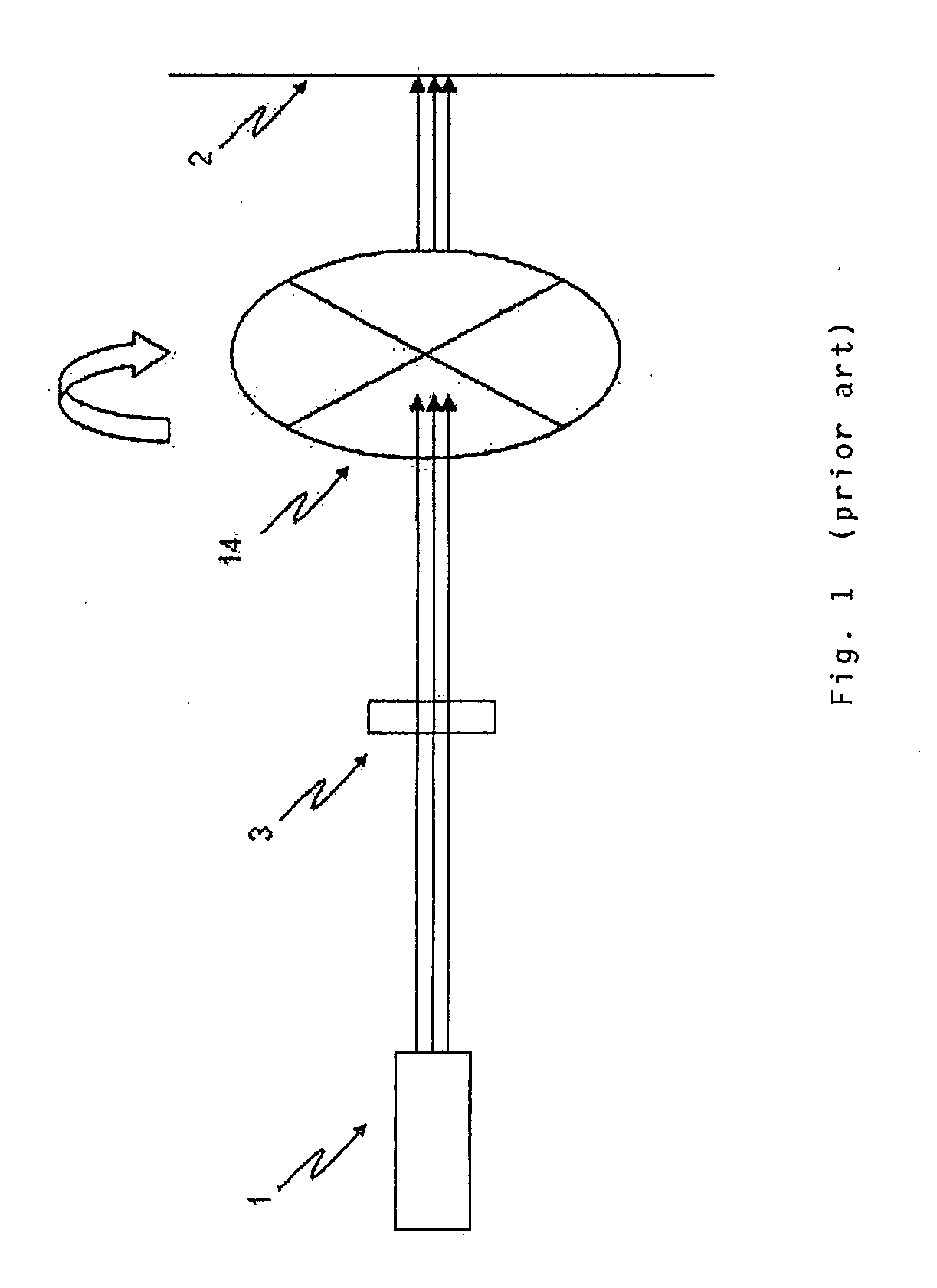
[0026]FIG. 1 is a schematic and simplified view of a projector system which can project images to be perceived as three-dimensional as is known for example from DE 196 26 097 C1. Light is conducted here from a light source 1 through a lens system 3 in the direction of the arrows. Omitted for purposes of simplification is the image generator as necessary to display images with such a projector system. A rotatable polarization wheel 14 shown with the example of four sectors, which in this illustration of the embodiment is arranged behind the lens system 3, ensures that the individual half-images generated will be polarized differently. For example, the half-image for the left eye will be polarized horizontally, the half-image for the right eye vertically. The continuously rotating polarization wheel thereto synchronously alternates polarization direction with the generation of the half-images. Due to the differing polarizations, a viewer wearing glasses provided with the appropriate p...


PUM


Abstract

A device for the large-screen projection of digital images onto a projection screen having a light source and a reflector for producing a cone of light and for projecting the light emitted by the light source through an image generator and an object lens onto the projection screen and having a 3D-sectored polarization wheel which can be driven by a motor and which comprises polarizing sectors in the optical path of the light emitted by the light source, wherein the motor of the polarization wheel is configured such that it can drive the wheel in increments, and an electronic control unit is provided which synchronizes the motor of the polarization wheel and synchronizes with the image sequencing of the image generator such that each individual image is projected through the polarizing sector associated with its polarization.

Description

BACKGROUND OF THE INVENTION[0001]The invention relates to a device for the large-screen projection of digital images onto a projection screen, said device having a light source and a reflector for producing a cone of light and for projecting the light emitted by the light source through an image generator and an object lens onto the projection screen and having a motor-drivable 3D-sectored polarization wheel having polarizing sectors in the optical path of the light emitted by the light source. The invention further relates to a method for the large-screen projecting of digital images onto a projection screen in which a light source emits light which produces a cone of light by means of a reflector and projects it through an image generator and an object lens onto the projection screen and in which a motor-drivable 3D-sectored polarization wheel having polarizing sectors rotates in the optical path of the light emitted by the light source.[0002]The method of spatial image projection...

Claims


Application Information

Patent Timeline
IPC IPC(8): G03B21/14
CPCG03B35/26G03B21/14G03B35/16
Inventor DOBLER, CHRISTOPH
Owner KINOTON
Learn More