
Endoscope guiding tube device

a technology of guiding tube and endoscope, which is applied in the field of can solve the problems of increasing the inability of the endoscope guiding tube device to be inserted into the body cavity, and the change of the fixed shape, so as to increase the friction to be produced, the size of the endoscope guiding tube device is inevitably increased, and the drawing mechanism is large and sturdy

Inactive Publication Date: 2009-03-05
HOYA CORP
View PDF12 Cites 59 Cited by
  • Summary
  • Abstract
  • Description
  • Claims
  • Application Information

AI Technical Summary

Benefits of technology

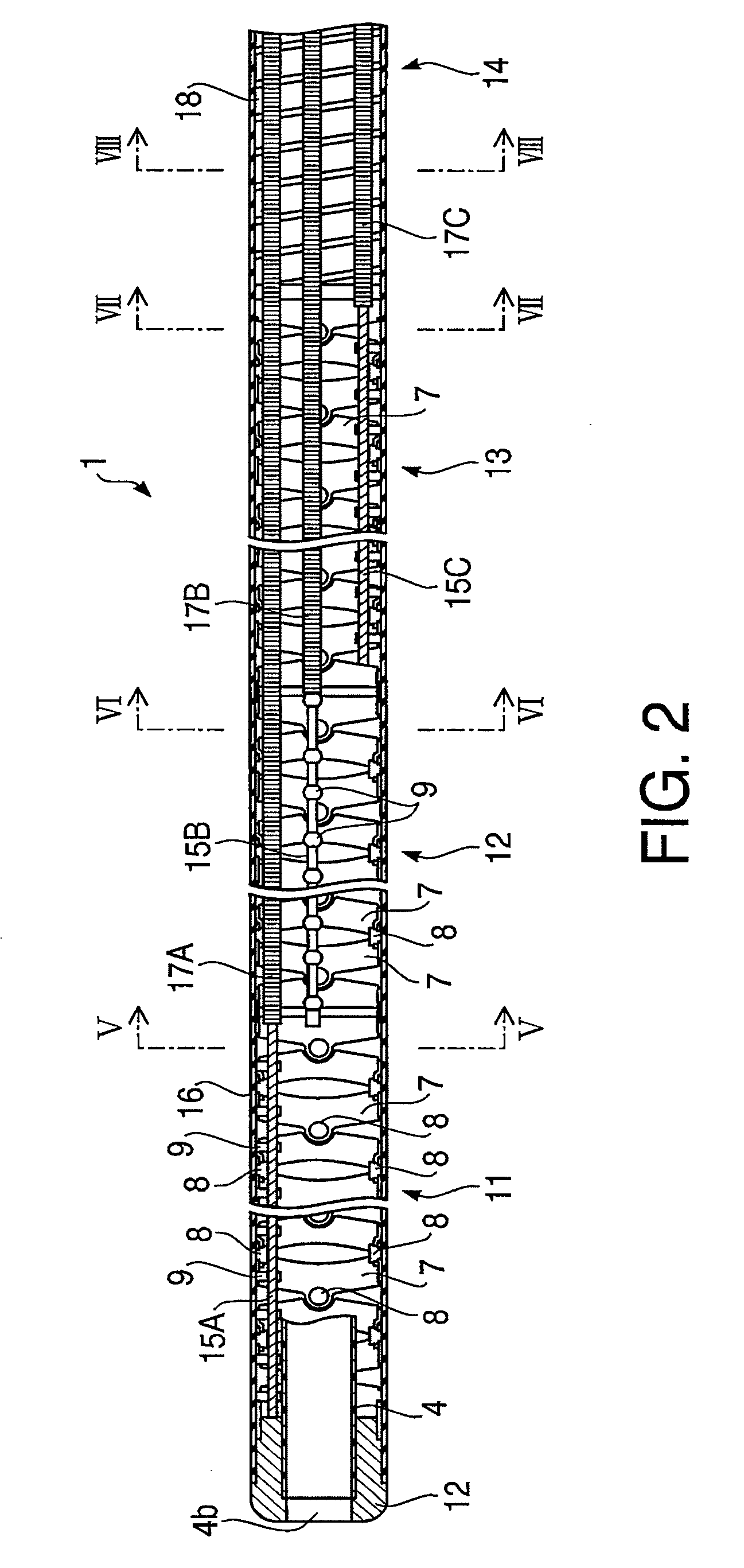
The present invention provides an endoscope guiding tube device that can bend passively in response to changes in the shape of the flexible endoscope, while maintaining a stable shape. The device includes a flexible insertion tube with a flexible channel for inserting the endoscope, and a bending portion formed by a plurality of barrel-shaped joint rings coupled together. The bending portion is deformable in all directions, and the device only requires a locking mechanism for securing the shape-holding wires. The device is light and easy to use, and its size can be reduced easily. The bending portion is designed to have a flexible tube with a flexible channel for inserting the endoscope, and the device includes a sealing member to seal the gap between the endoscope and the channel. The bending portion can be positioned on the front side of the flexible insertion tube, and an outer sheath can be used to cover the bending portion. The wire locking mechanism includes a fixing base with a cone-shaped outer surface and the plurality of shape-holding wires.

Problems solved by technology

However, such a structure of the endoscope guiding tube device requires a drawing mechanism for drawing strongly the wires (or the mesh tube).
Therefore, a size of the endoscope guiding tube device is inevitably increased.
Further, such an endoscope guiding tube device has a drawback that when an external force acts on the joint members in the fixed shape, adjacent ones of the joint members may slide with respect to each other and thereby the fixed shape is changed.
In this case, the endoscope guiding tube device can not be inserted into a body cavity from a mouth of a person.

Method used


Image

  • Endoscope guiding tube device
  • Endoscope guiding tube device
  • Endoscope guiding tube device

Examples


Embodiment Construction

[0048]Hereinafter, an embodiment according to the invention is described with reference to the accompanying drawings.

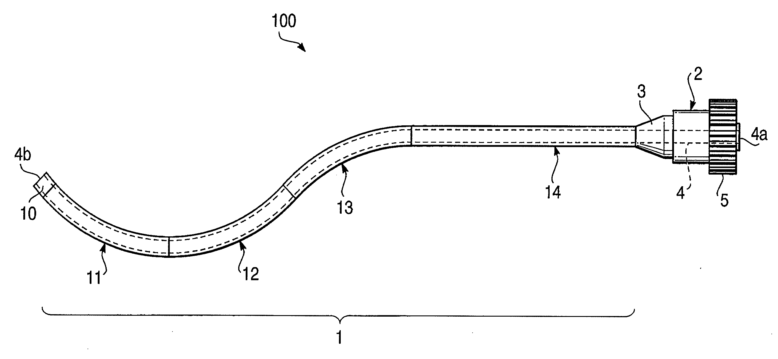
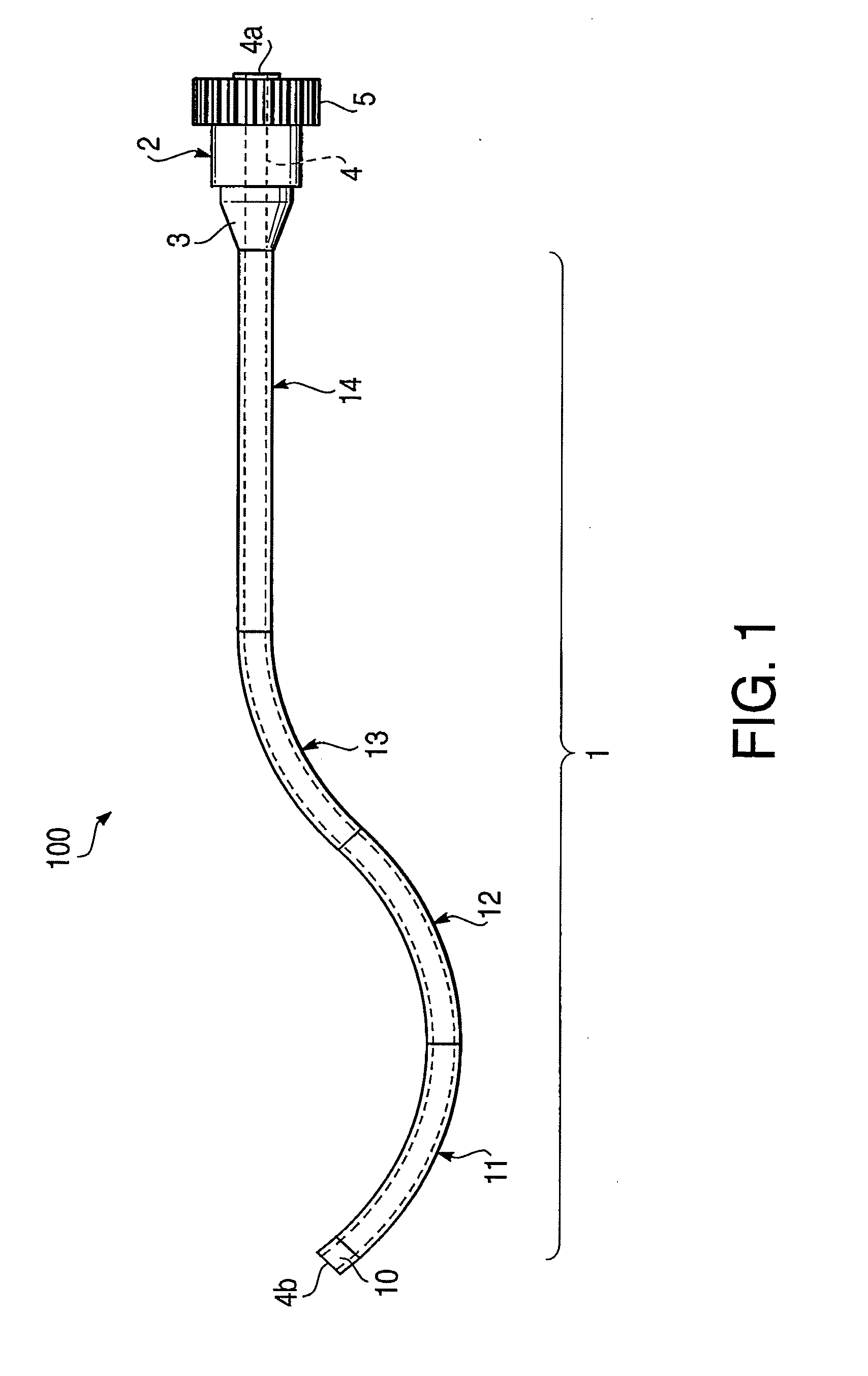
[0049]FIG. 1 illustrates an entire configuration of an endoscope guiding tube device 100 according to an embodiment of the invention. The endoscope guiding tube device 100 includes a flexible insertion tube 1 and an operation unit 2. The flexible insertion tube 1 is configured to be able to bend freely in all directions and can be inserted into a body cavity. The operation unit 2 is attached to a proximal end of the flexible insertion tube 1.

[0050]At a connection part between the operation unit 2 and the proximal end of the flexible insertion tube 1, a safety stopper 3 made of elastic material (e.g., rubber) is attached so as to prevent the flexible insertion tube 1 from buckling at the proximal end portion thereof. The safety stopper 3 has a tapered end.

[0051]The flexible insertion tube 1 has bending portions 11, 12 and 13 connected in series from a tip end thereof. ...


PUM


Abstract

There is provided an endoscope guiding tube device including a flexible insertion tube, an endoscope guiding channel arranged in the flexible insertion tube along, at least one bending portion having a framework including a plurality of barrel-shaped joint rings coupled to each other in series to be rotatable with respect to each other, a plurality of shape-holding wires of which tip ends are attached to a tip portion of the at least one bending portion, and an operation unit in which proximal ends of the plurality of shape-holding wires are movable freely in an axial direction. The operation unit includes a wire locking mechanism having a function of locking together all of the proximal ends of the plurality of shape-holding wires and a function of releasing a locked state of all of the proximal ends of the plurality of shape-holding wires.

Description

BACKGROUND OF THE INVENTION[0001]The present invention relates to an endoscope guiding tube device inserted into a body cavity together with an insertion unit of a flexible endoscope to maintain the attitude and orientation of the insertion unit of the endoscope.[0002]Conventionally, surgical operations for a target in an abdominal cavity (e.g., an operation for surgically removing a cholecyst) were conducted as an abdominal operation where an abdominal part of a patient is cut. However, recently, laparoscopically assisted surgery where a laparoscope (i.e., a rigid endoscope) or a surgical instrument is inserted into an abdominal cavity through a few holes opened in an abdominal part of a patient has become widespread. In general, each of such holes opened in an abdominal part of a patient has a size of a few centimeters. Therefore, if a patient undergoes laparoscopically assisted surgery, scars are left on a body surface in the abdominal part of the patient. It takes a certain time...

Claims


Application Information

Patent Timeline
Patent Type & Authority Applications(United States)
IPC IPC(8): A61B1/04
CPCA61B1/00154A61B1/0052A61B1/0057A61B1/273A61B1/00078A61B1/0055
Inventor UEDA, HIROHISAOHSHIMA, YUICHIICHIKURA, SHIGERUMUKUMOTO, TORUOTSUKA, TOSHIHIKONAKAMURA, TETSUYA
Owner HOYA CORP
Learn More