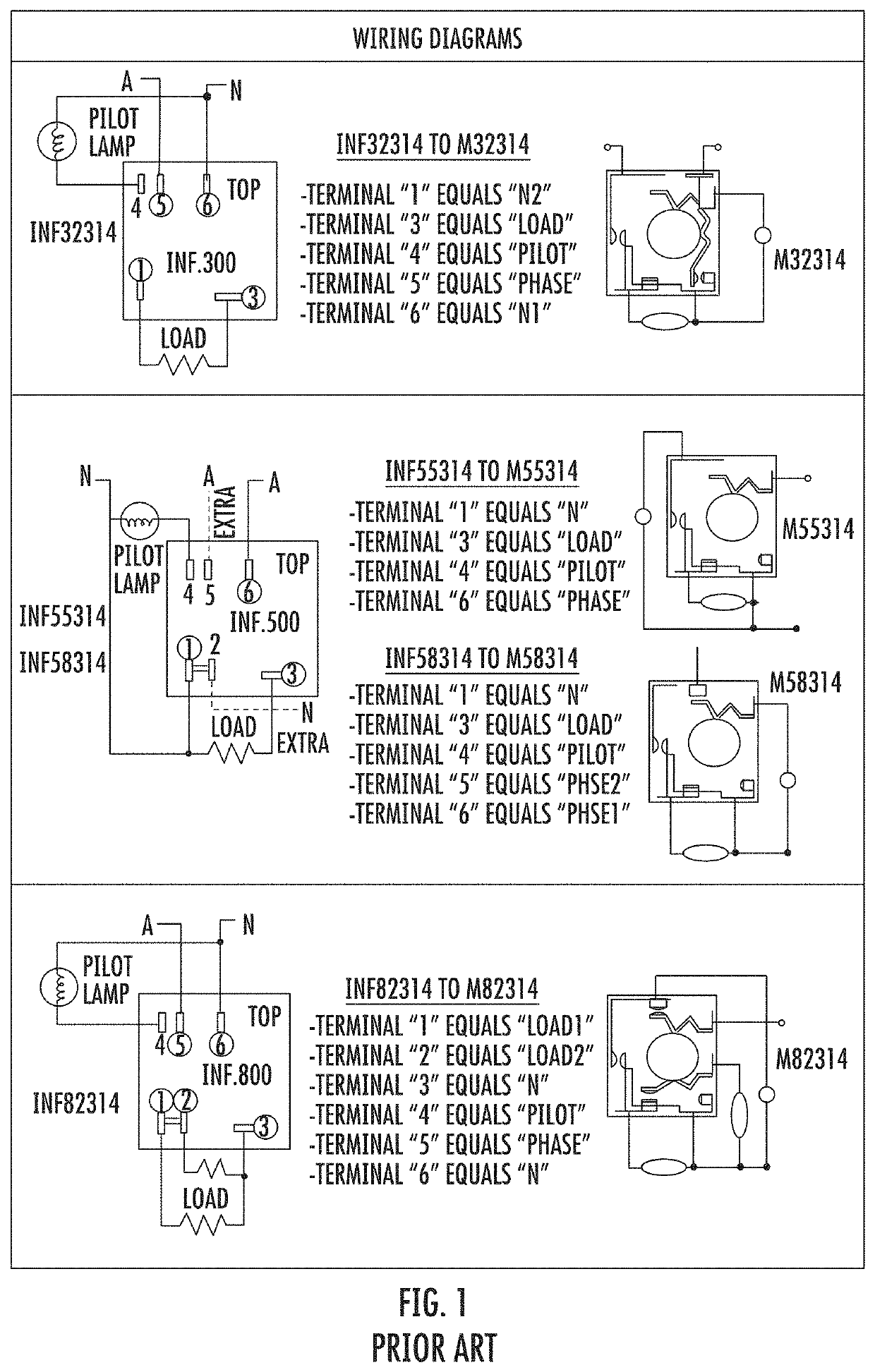
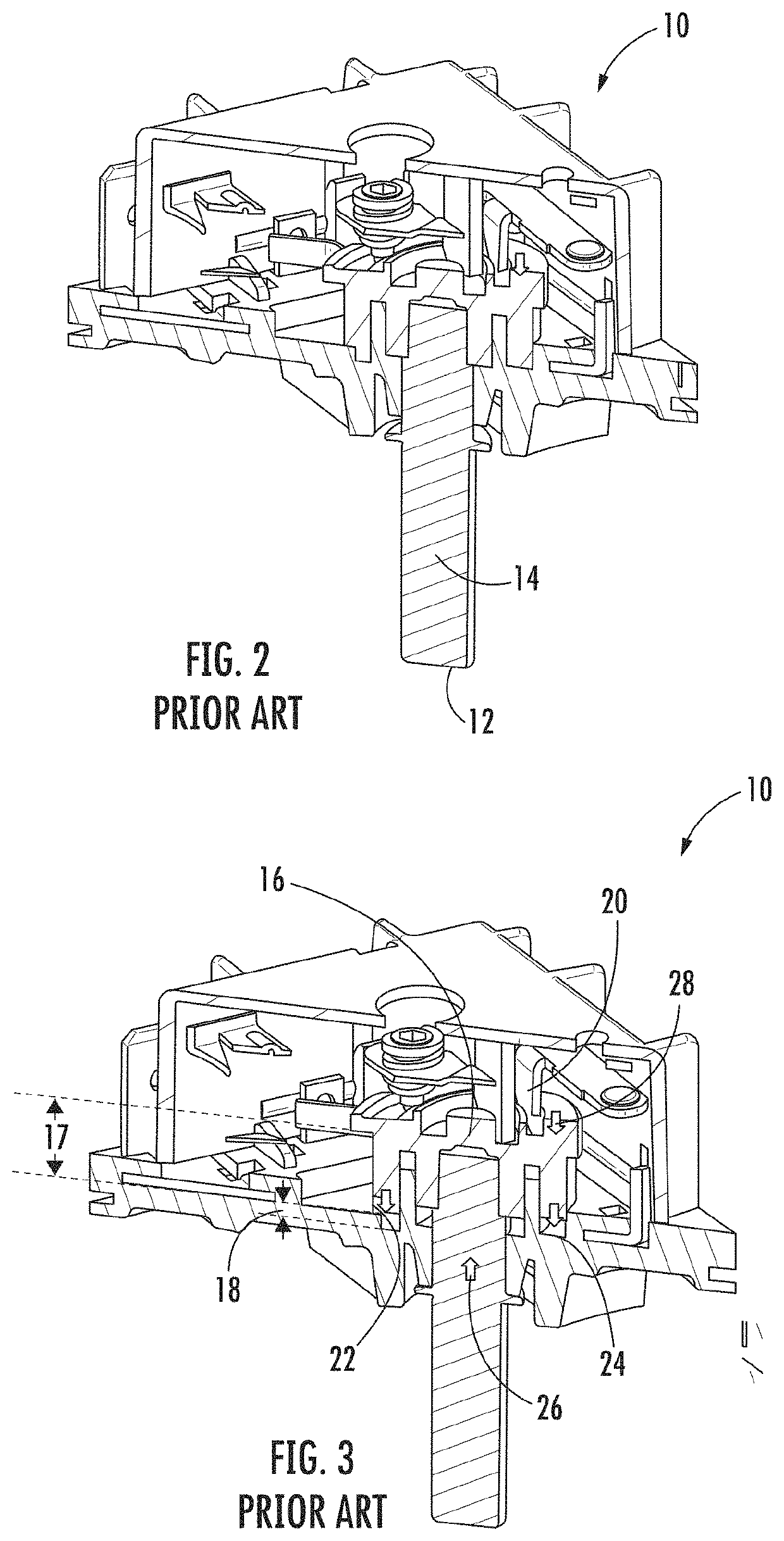
Increased push travel alternative for energy regulator
a technology of energy regulators and push rods, which is applied in the direction of electric switches, electric apparatus, emergency protective devices, etc., can solve the problems of single-piece cams, shafts b>14/b> or two-piece press fitting assemblies that are safe and functional, and cannot achieve the new torque standard of 4 nm according to ul en 60730-2-11, etc., to achieve improved shaft wobble, reduce the chance of cam cracking, and improve the effect of shaft wobbl
- Summary
- Abstract
- Description
- Claims
- Application Information
AI Technical Summary
Benefits of technology
Problems solved by technology
Method used
Image

Examples
Embodiment Construction
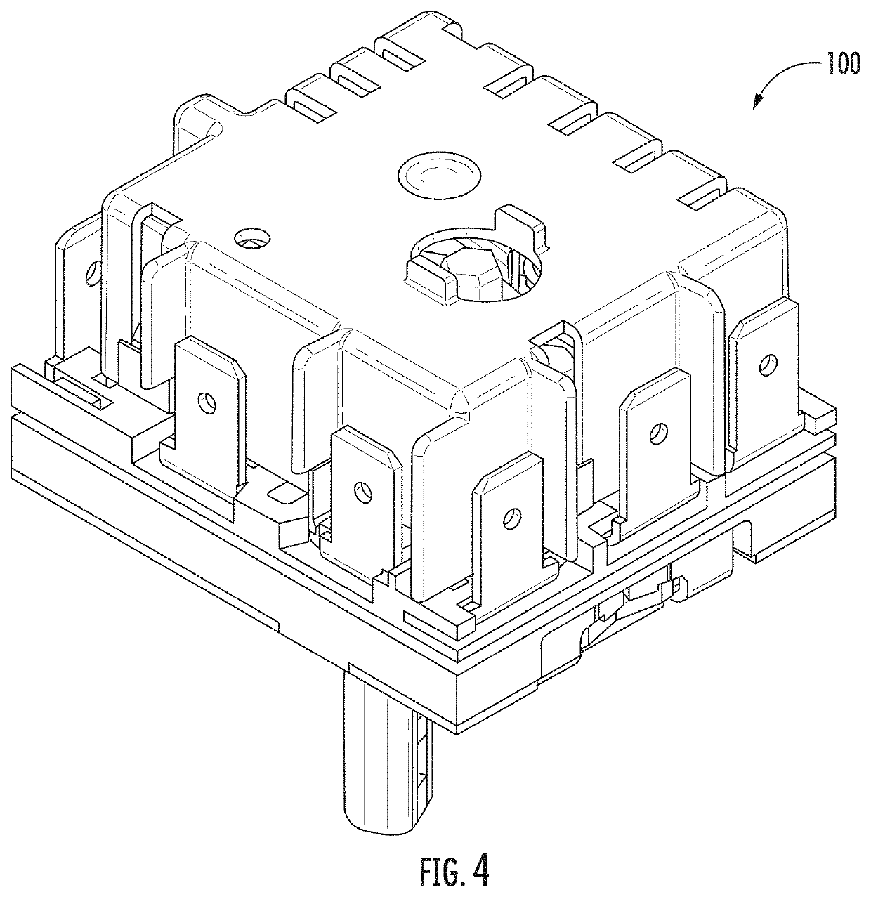
[0027]Turning now to the drawings, there is illustrated in FIG. 4 an exemplary embodiment of an infinite switch 100 according to the teachings of the invention. While such an exemplary embodiment will be utilized in describing various features and advantages of embodiments of the invention, such a description should be taken by way of example and not by limitation. Indeed, advantages of embodiments of the invention can be used to improve infinite switches where it is desirable to improve the reliability and life of the infinite switch 100.
[0028]FIG. 5 illustrates an exploded view of the infinite switch 100 having a push to turn assembly 101 that includes a floating shaft 102 moveable in a direction parallel to a shaft longitudinal axis 104 within a cam 106 to control the power to a load (not illustrated), typically a burner of a heating appliance.
[0029]The push to turn assembly 101 of the infinite switch 100 includes a base 108. The base 108 may be a wall fixed within the infinite s...
PUM
 Abstract
Description
Claims
Application Information
 - R&D
- Intellectual Property
- Life Sciences
- Materials
- Tech Scout
- Unparalleled Data Quality
- Higher Quality Content
- 60% Fewer Hallucinations
Browse by: Latest US Patents, China's latest patents, Technical Efficacy Thesaurus, Application Domain, Technology Topic, Popular Technical Reports.
© 2025 PatSnap. All rights reserved.Legal|Privacy policy|Modern Slavery Act Transparency Statement|Sitemap|About US| Contact US: help@patsnap.com