Method, system and device for data transfer in an optical network

a data transfer and optical network technology, applied in the field of passive optical networks, can solve the problems of increasing the complexity and cost of the device, increasing the bit error rate of downstream data, increasing the cost of data transfer, etc., and achieves the effects of boosting the development of wdm-pon, saving energy, and reducing the complexity of the system and the device cos

Active Publication Date: 2009-03-05
HUAWEI TECH CO LTD
View PDF20 Cites 13 Cited by
  • Summary
  • Abstract
  • Description
  • Claims
  • Application Information

AI Technical Summary

Benefits of technology

[0029]It can be seen from the above solutions that in the embodiments of the invention, the upstream data and the downstream data are transmitted by an asymmetric transmission mode, i.e., the ratio of the first rate for downstream optical signal transmission to the second rate for upstream optical signal transmission is greater than 1. Thus, the downstream optical signal used as carrier and the upstream optical signal are differentiated effectively, so that a synchronization device such as clock recover is not needed when remodulation is performed on

Problems solved by technology

Furthermore, large amount of energy is wasted when spectrally slicing the broadband light source, so that the cost of data transfer is increased.
It can be seen that although the downstream light may be used as the carrier light source for the upstream data in the prior art, the existing devices need to be modified, and a synchronization device needs to be added, which increases the complexity and cost of the devices.
Furthermore, although the optical power of the corresponding downstream optical signal is

Method used


Image

  • Method, system and device for data transfer in an optical network
  • Method, system and device for data transfer in an optical network
  • Method, system and device for data transfer in an optical network

Examples


first embodiment

[0071]FIG. 6 is a schematic diagram showing the structure of a system for data transfer in the WDM-PON. As shown in FIG. 6, in the embodiment of the invention, the system for data transfer in the WDM-PON includes a central office device, a remote wavelength division multiplexing / demultiplexing (MUX / DEMUX) device and N user devices, where N is an integer greater than 1, such as 1, 2, 3, . . . .

[0072]The central office device 61 includes N transmitting module 611, N receiving module 612 and a central office MUX / DEMUX device 613. Corresponding to each user device 63, there are a transmitting module 611 and a receiving module 612 operating in a specific wavelength in the central office device respectively.

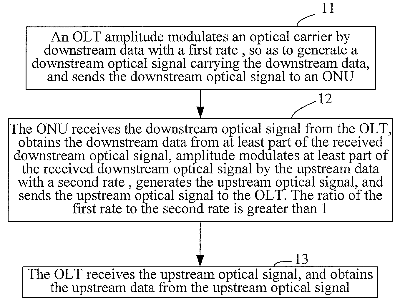
[0073]The transmitting module 611 is adapted to modulate with a first rate the downstream data onto the optical carrier, generate a downstream optical signal carrying the downstream data, and send the downstream data to a remote MUX / DEMUX device 62 with the downstream optical signal vi...

second embodiment

[0099]FIG. 7 shows the structure of the system for data transfer in the WDM-PON in an embodiment of the invention. As shown in FIG. 7, in this embodiment, the system for data transfer in the WDM-PON includes a central office device, a remote MUX / DEMUX device and N user devices, where N is an integer greater than 1, such as 1, 2, 3, etc.

[0100]In this embodiment, the central office device is OLT 71, the remote MUX / DEMUX device is remote AWG 72, and the user device is ONU 73.

[0101]The OLT 71 includes N transmitting modules 711, N receiving modules 712, a central office MUX / DEMUX device and a circulator 714. Here the central office MUX / DEMUX device includes central office AWG 713a and central office AWG 713b. A respective transmitting module 711 and receiving module 712 are included in the OLT 71 corresponding to each ONU 73.

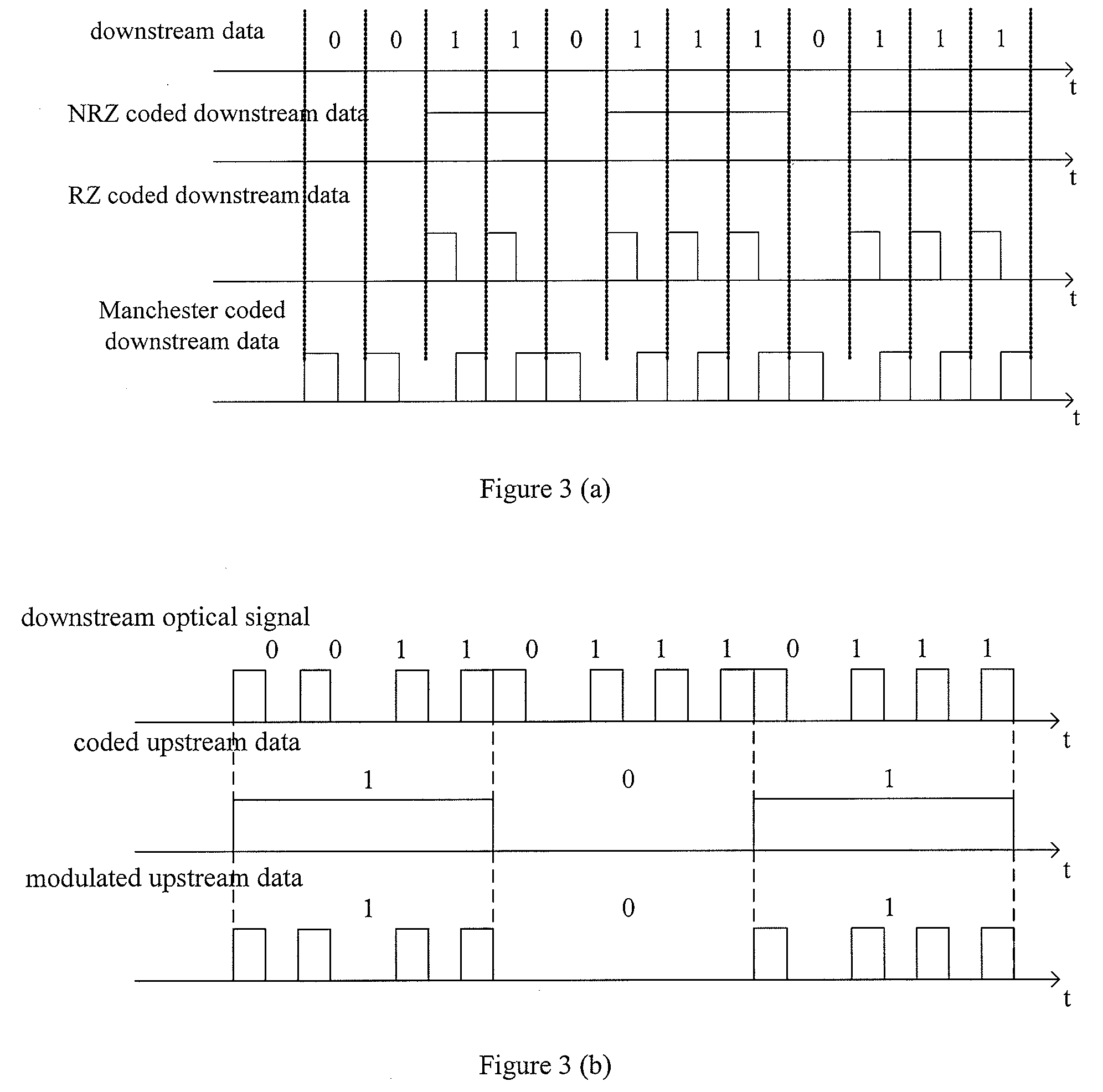
[0102]A Manchester coding module 711a in the transmitting module 711 performs Manchester coding on the downstream data, send the coded downstream data to a direct m...

third embodiment

[0111]FIG. 8 shows the structure of the system for data transfer in the WDM-PON according to an embodiment of the invention. As shown in FIG. 8, the system for data transfer in the WDM-PON according to this embodiment of the invention includes a central office device OLT 81, a remote AWG 72 and ONUs 73.

[0112]In this embodiment, the remote AWG 72 and N ONUs 73 are the same as the remote AWG 72 and ONUs 73 in the embodiment as shown in FIG. 7, which will not be illustrated here again. The receiving module 712 and the central office AWG 713a as well as the central office AWG 713b in the OLT 81 are the same as the receiving module 712 and the central office AWG 713a as well as the central office AWG 713b in the embodiment as shown in FIG. 7, which will not be illustrated here again. In this embodiment, the Manchester coding module 711a in the transmitting module 811 is the same as the Manchester coding module 711a in the embodiment as shown in FIG. 7, which will not be illustrated here ...


PUM


Abstract

A method for data transfer in an optical network, including: amplitude modulating, by a central office, an optical carrier by a downstream data with a first rate to generate a downstream optical signal carrying the downstream data; sending the downstream optical signal to a user terminal; obtaining, by the user terminal, the downstream data from the downstream optical signal; amplitude modulating, by the user terminal, the downstream optical signal by an upstream data with a second rate to generate an upstream optical signal, wherein the ratio of the first rate to the second rate is greater than 1; sending the upstream optical signal to the central office; and receiving, by the central office, the upstream optical signal, and obtaining, by the central office, the upstream data from the upstream optical signal. Furthermore, the present invention discloses a system and device for data transfer in the optical network. With the invention, the complexity of the system may be effectively reduced, and the cost of the device may be lowered.

Description

[0001]The present application claims the priority of CN Application No. 200710090058.X filed on Mar. 23, 2007, titled “METHOD, SYSTEM AND DEVICE FOR DATA TRANSFER IN A WDM-PON,” which is incorporated herein by reference in its entirety.FIELD OF THE INVENTION[0002]The present invention relates to the technical field of passive optical network, and in particular, to a method, a system and a device for data transfer in an optical network.BACKGROUND OF THE INVENTION[0003]In a wavelength division multiplex-passive optical network (WDM-PON), data is transferred in a manner that the optical network unit (ONU) exclusively uses the upstream / downstream wavelengths. In the WDM-PON, different ONUs on the user terminal adopt different operation wavelengths, i.e., the carrier wavelengths used by ONUs for sending the upstream data are different. In order to avoid the case that the ONU devices are different result from lasers of different wavelengths are to be arranged on the ONUs, a colorless ONU ...

Claims


Application Information

Patent Timeline
IPC IPC(8): H04B10/00H04B10/2587H04B10/272
CPCH04B10/2587H04B10/272H04J14/0226H04J14/0282H04J2014/0253H04Q2011/0032H04Q2011/0035H04J14/0246H04J14/025H04Q11/0067
Inventor LIN, HUAFENGYU, FAN
Owner HUAWEI TECH CO LTD
Why Eureka
Try Eureka