Liquid crystal display device with improved display luminance
a display device and liquid crystal technology, applied in the direction of instruments, static indicating devices, etc., can solve the problems of color purity dropping and color breakage phenomenon, and achieve the effect of improving display luminan
- Summary
- Abstract
- Description
- Claims
- Application Information
AI Technical Summary
Benefits of technology
Problems solved by technology
Method used
Image

Examples
eleventh embodiment
[0280]The present inventor has studied a display method for a liquid crystal display unit and has invented a display method of displaying a partial display area with the same color always during one frame and displaying the other display area with a plurality of colors by FS driving.
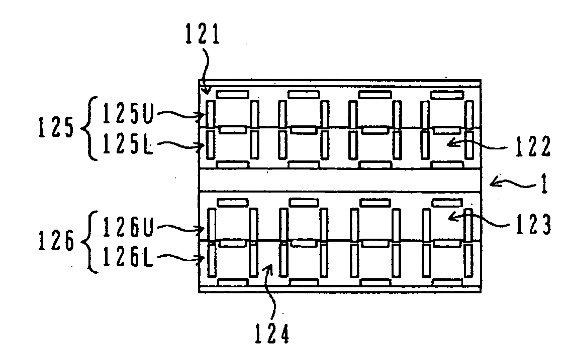
[0281]FIG. 32A shows a display example 1 of a liquid crystal display unit. In the display example 1, a clock display unit is disposed at an upper stage, a temperature display unit is disposed at a lower stage, and the clock display unit is always white display. Color of the temperature display unit is desired to be changed.
[0282]In FIG. 32A, a segment 1 displays “AM” of the clock display unit in white display color. A segment 2 displays “: (colon)” of the clock display unit in white display color. 7-segment units of four digits of the clock display unit are also displayed in white display color. A segment 3 displays “TEMP” at the left of the temperature display unit in white display color. A segment 4 di...
embodiment 11-1
[0288]Next, voltage waveforms are shown to be applied to each common electrode and each segment electrode. In this example, description will be made by using an NWTN type having a metal black mask in a non-display area.
[0289]FIG. 33 is a timing chart showing timings of drive waveforms applied to common electrodes 1 to 4 and segment electrodes 1 to 6 in one frame and emission of the backlight areas A and B. Emission colors are also shown. A color break-less driving method is used as the FS driving method. As one frame is set to about 16.7 ms, the number M of subframes is set to “3” because four display colors, white (W), red (R), blue (B) and black (BK), are used. The frame is divided at equal pitch into subframes of about 5.57 ms each. A voltage applied to the liquid crystal display unit is a multiplex drive voltage at a 1 / 4 duty, a 1 / 3 bias and a frame frequency f of 360 Hz. The number N of all scan (common) lines is “4”, and a scan standby time C is set to about 2.09 ms from C=(N−...
embodiment 11-2
[0292]Description will be made on a method of improving a display luminance of the area B. In order to improve a display luminance of the area B, it is sufficient if an emission time per subframe is prolonged.
[0293]FIG. 34 shows an assignment example 2 of backlight areas. As shown, the present inventor divides the area into three areas A, B and C. The area A corresponds to a clock display unit, the area B corresponds to a left temperature display unit, and the area C corresponds to a right temperature display unit. Emission of black+two colors (two colors may differ in the areas B and C) was performed. In this manner, an emission time per subframe is prolonged by reducing the subframe number M to “2”.
[0294]FIG. 35 is a timing chart showing timings of drive waveforms applied to common electrodes 1 to 4 and segment electrodes 1 to 6 and emission of the backlight areas A, B and C. Emission colors are also shown. One frame time is the same as that of the embodiment 11-1, the subframe nu...
PUM
 Abstract
Description
Claims
Application Information
 - R&D
- Intellectual Property
- Life Sciences
- Materials
- Tech Scout
- Unparalleled Data Quality
- Higher Quality Content
- 60% Fewer Hallucinations
Browse by: Latest US Patents, China's latest patents, Technical Efficacy Thesaurus, Application Domain, Technology Topic, Popular Technical Reports.
© 2025 PatSnap. All rights reserved.Legal|Privacy policy|Modern Slavery Act Transparency Statement|Sitemap|About US| Contact US: help@patsnap.com