
Microfluidic Pump and Valve Structures and Fabrication Methods

a technology of microfluidic pumps and valves, applied in the field of microfluidics, can solve the problems of inability to manufacture components, inability to meet the requirements of the application, etc., and achieves the effects of easy manufacturing, convenient manufacturing, and robust system

Active Publication Date: 2009-03-05
RHEONIX INC
View PDF6 Cites 12 Cited by
  • Summary
  • Abstract
  • Description
  • Claims
  • Application Information

AI Technical Summary

Benefits of technology

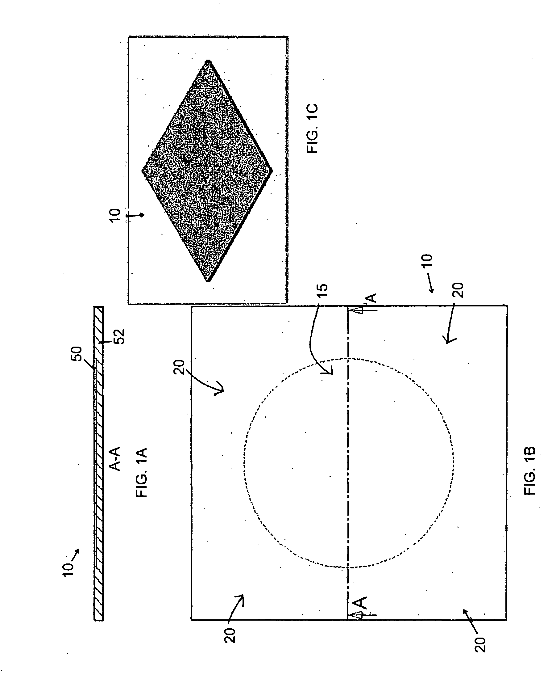
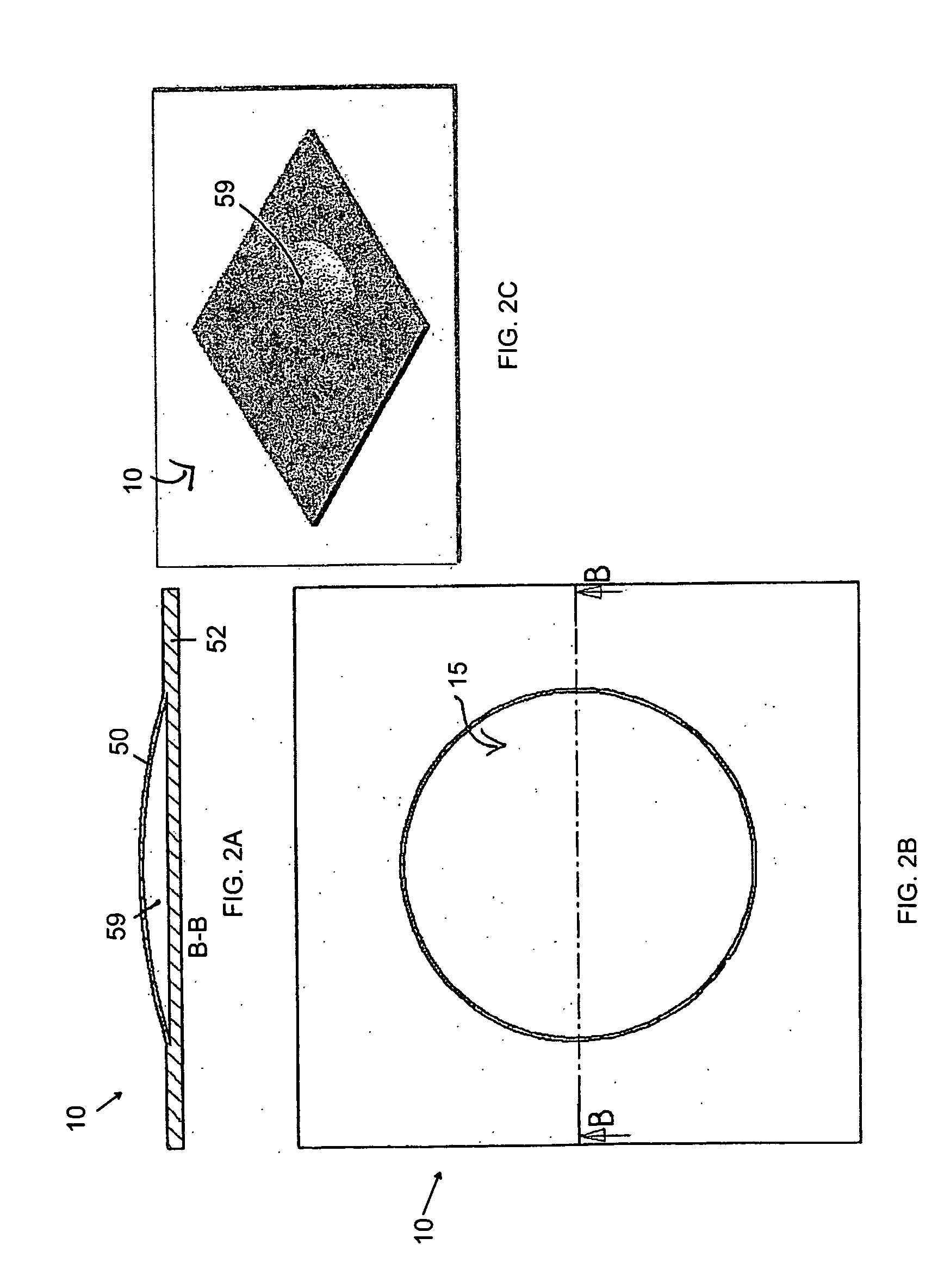
"The patent describes a microfluidic device that includes a rigid plastic membrane that can be actuated between a relaxed state where it lies against a substrate and an actuated state where it is moved away from the substrate. This membrane can be easily manufactured and used to create valves, pumps, and other components of a microfluidic system. The device can also have a second rigid plastic substrate that contacts and joins with the membrane, allowing for the creation of more complex structures. The membrane has a unbonded region that can be moved to create a cavity for fluid flow between channels in the substrate. The device can also have a shared valve structure with multiple pumps, or a shared valve structure that includes a membrane above multiple microchannels. Overall, the device provides a flexible and robust system for manipulating fluids in microfluidic applications."

Problems solved by technology

However, the material and production costs of the inorganic chips may become prohibitively high especially when the fluidic pathway(s) requires significant area or the chip has to be disposable.
The research effort required to redevelop these assays on inorganic surfaces would require significant time and resource investments.
However, there are remaining obstacles.
Although, the materials employed to manufacture microfluidic devices are becoming less expensive, the actual costs of these devices will not become sufficiently low for mass use until the costs of manufacturing these components also decreases.
However, the fabrication of polymeric microfluidic chips presents a variety of challenges and with these challenges come low yields and higher costs.
Unfortunately, these techniques often significantly alter the mated surfaces and yield distorted or completely blocked microfluidic pathways due, for example, to the low dimensional rigidity of polymeric materials under the aforementioned bonding conditions.
Once the device is assembled, any blockage or obstruction in a channel is difficult or impossible to reverse.
The result is that the device is lost and the manufacturing yield is lowered.
Even if the loss were acceptable, the manufacturing process is often costly because each device must be independently designed for each application.
These systems tend to be much larger in volume than the microfluidic systems they connect to, causing problems with flow control resolution and accuracy.
This causes great difficulty with separations, mixing, and other microfluidic functions.
However, very few possess the criteria necessary for integration into a complex microfluidic system.
Most require very complex fabrication sequences; producing the active component is such a sensitive and intricate process that very little window is left to integrate the rest of the microfluidic system.
One is left with an exquisite pump or valve with no effective way to connect or incorporate it into the microfluidic system.
Often the substrates and processes are prohibitively expensive for a disposable device.
Finally, the materials required to build the pump can interfere, or be incompatible with, the process the microfluidic system was intended to perform.
This builds substantial non-refundable engineering costs into product development and increases the cost of the product.

Method used


Image

  • Microfluidic Pump and Valve Structures and Fabrication Methods
  • Microfluidic Pump and Valve Structures and Fabrication Methods
  • Microfluidic Pump and Valve Structures and Fabrication Methods

Examples


Embodiment Construction

[0053]As used herein, the word “microstructure” generally refers to structural features on a microfluidic substrate component with walls having at least one dimension in the range of about 0.1 micrometer to about 1000 micrometers. These features may be, but are not limited to, microchannels, microfluidic pathways, microreservoirs, microvalves or microfilters. The term “polymeric” refers generally to a macromolecular structure or material having a molecular weight that is substantially higher than the constituent monomers and, which may be, but does not have to be, produced by a polymerization reaction. All materials commonly and herein referred to as “plastic” materials include polymeric materials. The term “acrylic” refers to materials including Acrylite®, Plexiglas®, PMMA and other trade names of polymethylmethacrylate. “Linear polymeric materials” generally include polymeric materials in which molecules form long chains without branches or cross-linked structures. A “two-dimensio...


PUM

PropertyMeasurementUnit
pressureaaaaaaaaaa
pressureaaaaaaaaaa
pressureaaaaaaaaaa

Abstract

Plastic microfluidic structures having a substantially rigid diaphragm that actuates between a relaxed state wherein the diaphragm sits against the surface of a substrate and an actuated state wherein the diaphragm is moved away from the substrate. As will be seen from the following description, the microfluidic structures formed with this diaphragm provide easy to manufacture and robust systems, as well readily made components such as valves and pumps.

Description

RELATED APPLICATION DATA[0001]This application is a divisional of U.S. application Ser. No. 11 / 242,694 filed on Oct. 3, 2005, which is a continuation-in-part of U.S. application Ser. No. 10 / 964,216 filed on Oct. 13, 2004, and claims the benefit of priority of the aforementioned applications.FIELD OF THE INVENTION[0002]Embodiments of the invention generally pertain to the field of microfluidics. In particular, embodiments of the invention pertain to microfluidic diaphragm structures, microfluidic chips, automated microfluidic reagent processing systems, and methods thereof.BACKGROUND OF THE INVENTION[0003]Technologies relating to systems and methods for manipulating minute volumes of fluids, such as biological and chemical fluids, are widely referred to as microfluidics. The realized and potential applications of microfluidics include disease diagnosis, life science research, and biological and / or chemical sensor development.[0004]A microfluidic structure including a substrate having...

Claims


Application Information

Patent Timeline
Patent Type & Authority Applications(United States)
IPC IPC(8): B29C65/54B29C65/52
CPCB01F5/0683Y10T156/1043B01F11/0071B01F13/0059B01L3/502707B01L3/50273B01L3/502738B01L2200/12B01L2300/0816B01L2300/0861B01L2300/0867B01L2300/0887B01L2400/0481B01L2400/0487B01L2400/06B01L2400/0638B01L2400/0655B01L2400/084B29C65/4895B29C66/004B29C66/54B29K2025/00B29K2033/08B29K2069/00B29K2101/12B29L2031/7496B29L2031/7506B29L2031/756B81B2201/036B81B2201/054B81C1/00103F04B43/043F04B43/06F16K99/0001F16K99/0015F16K99/0021F16K99/0034F16K99/0055F16K99/0057F16K99/0059F16K2099/0074F16K2099/0076F16K2099/0078F16K2099/008F16K2099/0084F16K2099/0094F15C1/08F16K7/12B29C66/5412Y10T29/49405Y10T156/1002B01F5/0688B29C66/71Y10T137/2202Y10T137/2218Y10T137/8593Y10T137/85978Y10T137/212F04B43/028B01F25/451B01F25/4521B01F31/65B01F33/30B29K2033/12B29K2025/06F04B43/026F04B53/10F04B15/00F05B2210/11Y10S417/00B01F2101/2202B29K2025/04B81B3/0021B81B2203/0127B81C1/00158
Inventor YOUNG, LINCOLN C.ZHOU, PENG
Owner RHEONIX INC
Learn More