Vtg Mechanism Assembly Using Wave Spring

a technology of wave springs and turbine wheels, which is applied in the direction of machines/engines, reaction engines, liquid fuel engines, etc., can solve the problems of cartridges not being held in the correct position relative to the turbine wheel, the amount of force applied to the cartridges could potentially be reduced, and the cartridges may not be able to relax and lose shap

Active Publication Date: 2009-02-26
BORGWARNER INC
View PDF10 Cites 12 Cited by
  • Summary
  • Abstract
  • Description
  • Claims
  • Application Information

AI Technical Summary

Benefits of technology

[0010]The heat shield prevents the spring member from being exposed to heat from the exhaust gases, and the cartridge includes vanes which can alter the flow of exhaust gas through the turbine.

Problems solved by technology

One common problem with the heat shield performing the function of holding the cartridge in place is that the heat shield comes in contact with the hot exhaust gas from the engine, and therefore could potentially relax and lose shape.
If the Belleville-washer-shaped heat shield relaxes and loses shape, the amount of force applied to the cartridge could potentially be reduced, and the cartridge may no longer be held in the correct position relative to the turbine wheel.
This large gap reduces efficiency if used with the standard wheel having scallops between the blades.
The gap also requires a relatively large distance between the turbine wheel and the bearing that supports the shaft which could lead to increased efficiency losses due to the required, increased radial clearance between the turbine wheel and turbine housing, and could lead to increased instability for the bearing.

Method used


Image

  • Vtg Mechanism Assembly Using Wave Spring
  • Vtg Mechanism Assembly Using Wave Spring

Examples


Embodiment Construction

[0015]The following description of the preferred embodiment(s) is merely exemplary in nature and is in no way intended to limit the invention, its application, or uses.

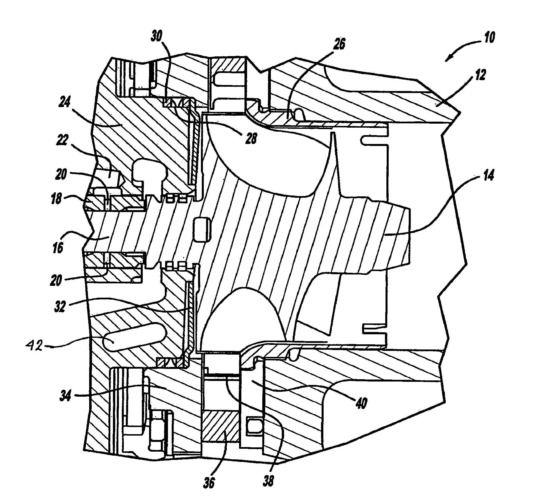
[0016]A turbocharger unit incorporating the present invention is generally shown at 10. There is a turbine housing 12, which surrounds a turbine wheel 14. The turbine wheel 14 is mounted on a shaft 16; the shaft 16 extends through, and is supported by, a set of bearings 18. The bearings 18 feature a set of oil passages 20, which are connected to a primary oil passage 22. The turbine housing 12 is connected to a housing or, an intermediate housing 24. The turbine housing 12 has a contoured sleeve 26 which circumferentially surrounds the turbine wheel 14.

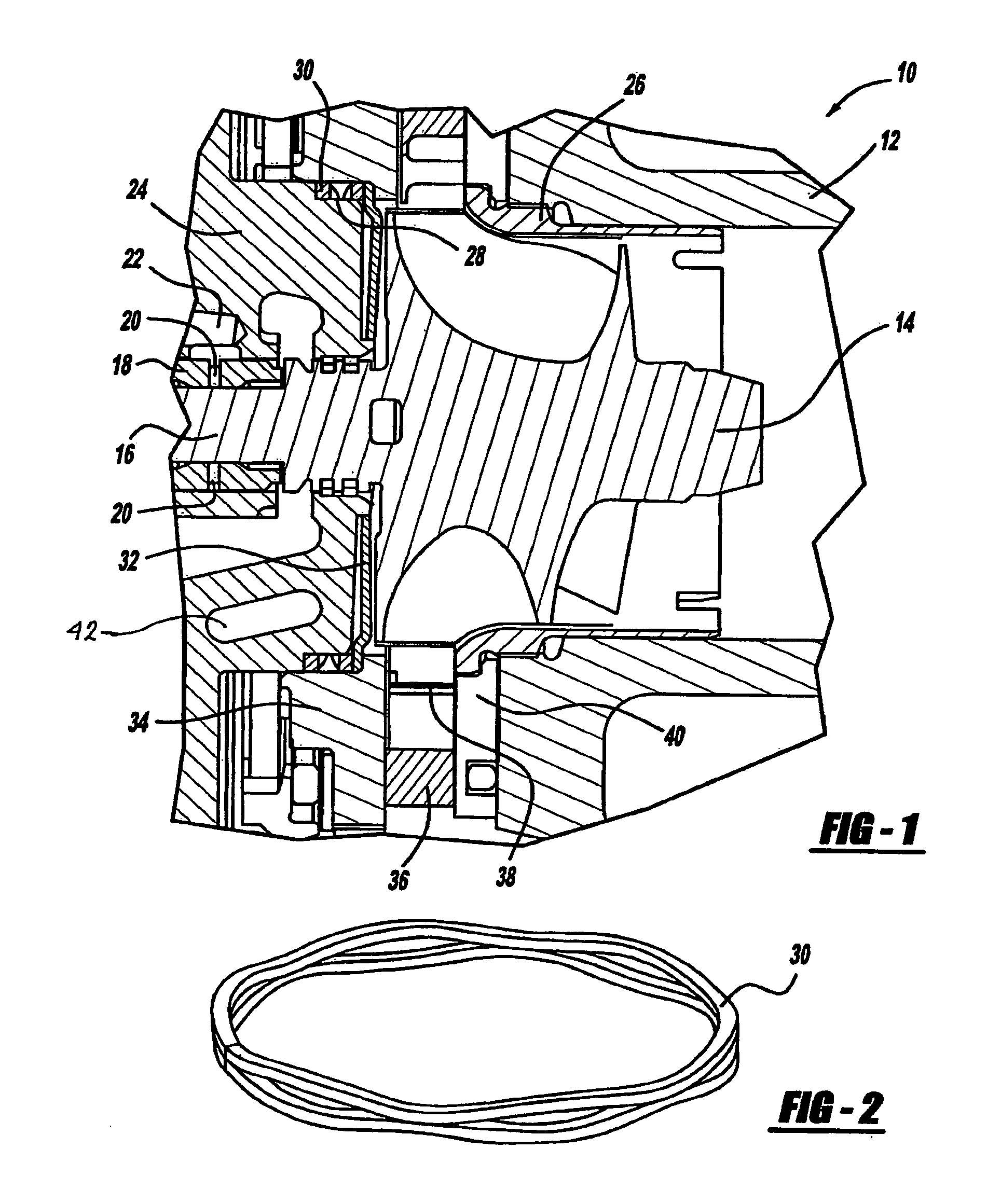
[0017]The intermediate housing 24 includes a recessed portion 28 for supporting a spring member, which in this embodiment is a wave spring 30. The wave spring 30 rests between the recessed portion 28, and a heat shield 32. The heat shield 32 also rests against a first d...


PUM


Abstract

The present invention is a turbocharger unit (10) incorporating variable turbine geometry. The unit (10) has a turbine for receiving exhaust gases from an engine having a turbine wheel (14) located inside a turbine housing (12), and an intermediate housing (24) connected to the turbine housing (12), having a recessed portion (28). A spring member is located in the recessed portion (28), and a heat shield (32) for receives apply force from the spring member. There is also a cartridge (36) for providing variable turbine geometry located between a first disk (34) and a second disk (40) in the turbine housing (12); the second disk (40) is held in contact with the turbine housing (12) by a contoured sleeve (26). The apply force received by the heat shield (32) from the spring member transfers through the first disk (34), the cartridge (36), and the second disk (40), locating the cartridge (36) in proximate relationship to the turbine wheel (14).

Description

CROSS-REFERENCE TO RELATED APPLICATIONS[0001]This application claims the benefit of U.S. Provisional Application No. 60 / 762,663, filed Jan. 27, 2006.FIELD OF THE INVENTION[0002]The present invention relates to variable turbine geometry turbochargers, the positioning of a set of vanes in relation to the turbine wheel, and how the vanes are held in place.BACKGROUND OF THE INVENTION[0003]Turbochargers are generally known and used for increasing power in both internal combustion and diesel engines. Exhaust gas is used to provide energy for a turbine, and the turbine drives a compressor which is typically mounted on a common shaft with the turbine. The compressor receives air from atmosphere, compresses it, and forces the air into the intake manifold of the engine. One feature commonly used in some turbochargers is the concept of variable turbine geometry (VTG). A turbocharger which employs the concept of VTG has the capability of varying the amount of exhaust gas flowing through the tur...

Claims


Application Information

Patent Timeline
Patent Type & Authority Applications(United States)
IPC IPC(8): F01D17/16F01D25/08F02C6/12
CPCF01D17/165F01D25/125F05D2260/30F05D2240/55F05D2250/611F05D2220/40F02C6/12
Inventor WARD, DANIEL
Owner BORGWARNER INC
Why Eureka
Try Eureka