
Aspirator assembly

a technology of aspirator and assembly, which is applied in the direction of suction devices, suction drainage containers, medical devices, etc., can solve the problems of increasing the possibility of infection, affecting the flow direction of air, and preventing the self-induction expulsion of mucus by blowing one's nose, etc., to facilitate the collection of mucus heavier, facilitate the casing, and facilitate the effect of flow direction

Inactive Publication Date: 2009-02-19
VISIOMED GRP SA
View PDF26 Cites 21 Cited by
  • Summary
  • Abstract
  • Description
  • Claims
  • Application Information

AI Technical Summary

Benefits of technology

[0010]The aspirator assembly further includes an inlet assembly connected to or formed as part of the removable cover. The inlet assembly is structured to further facilitate the direction of flow of the heavier, predetermined portion of the aspirated fluid into the collection container. Thereafter, the container and collected mucus portion of the aspirated fluid are collectively disposed of after the aspiration procedure has been completed. Accordingly, the contamination and possible reduction of health hazards are accomplished by allowing for the disposal and replacement of the collection container as versus its cleaning, after use.
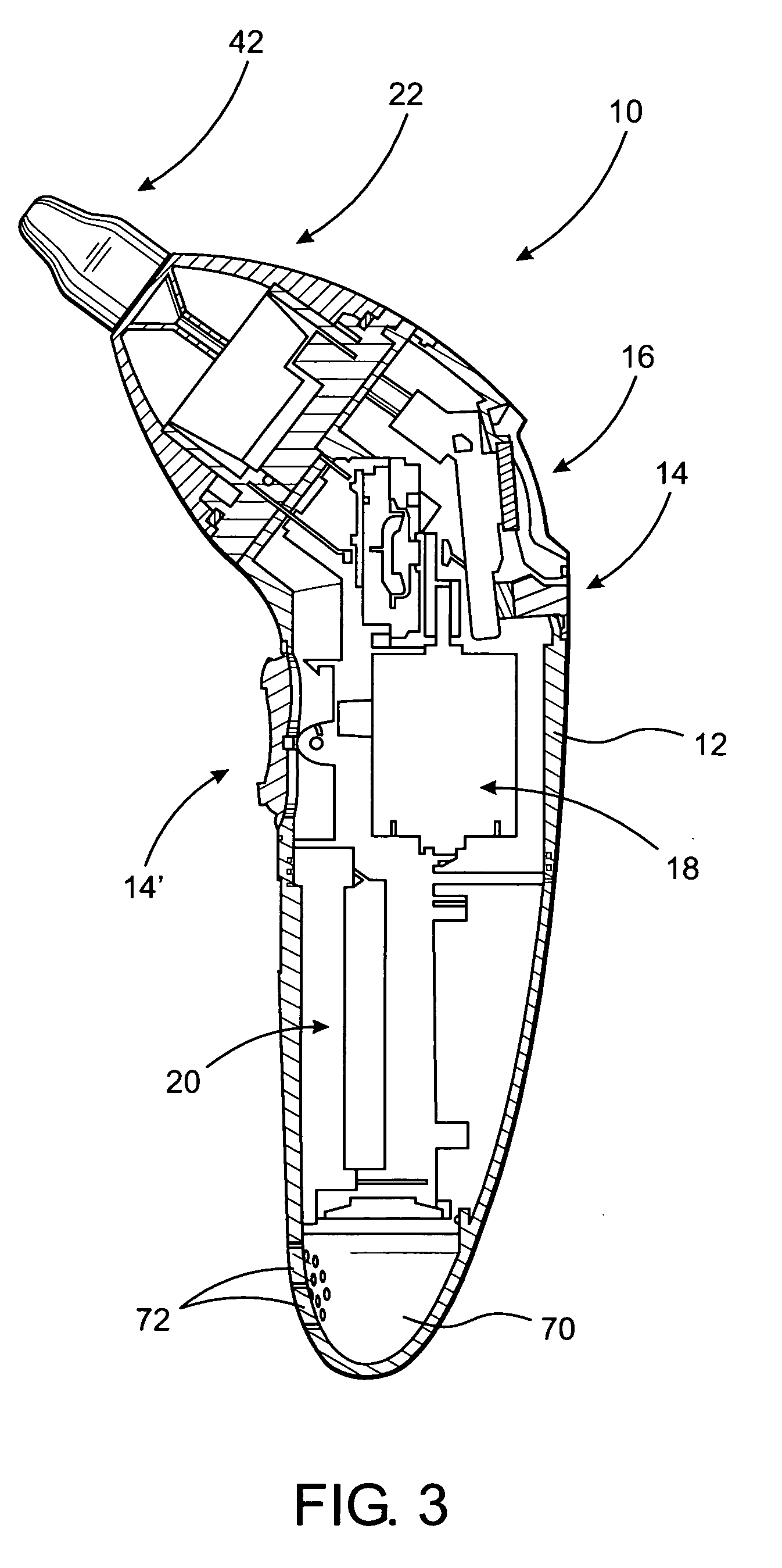
[0011]As will be explained in greater detail hereinafter, the negative pressure source and its power supply in the form of a battery pack are housed within a hollow interior of the casing and are respectively configured and dimensioned to facilitate the casing being held and operated by a single hand of a user or operator. As such, the vacuum or negative pressure created by the negative pressure source communicates with the receiving chamber and with the aforementioned inlet assembly. Upon the creation of a sufficient negative pressure, the direct application of the inlet assembly into an appropriate portion of the nasal cavity, will serve to remove the trapped and / or collected aspirated fluid. As set forth above and more fully explained hereinafter, the cooperative disposition and structuring of the inlet assembly in aligned relation with the interior of the collection container facilitates the collection of the heavier mucus or predetermined portion of the aspirated fluid into the interior of the container.
[0013]Other structural and operative features of the aspirating assembly include operative controls easily activated by one or more fingers of the user and a display, facilitating visualization of the various operative features and performance characteristics of the aspirating assembly during its activation, operation and overall use. Yet additional operative features and components of the aspirating assembly may include a sound generating assembly structured to produce music or other appropriate sounds, which may be especially appealing and therefore serve as a diversion to infants and children, during the aspirating procedure.

Problems solved by technology

The ordinary cold, as well as more serious respiratory infections, can result in the blockage of the nasal passage or cavity due to the accumulation of mucus therein.
However, in the case of small children or infants the self induced expulsion of the mucus by blowing ones nose typically has not been learned.
In addition, inordinate collection of certain fluids in the nasal passage or cavities significantly increases the possibility of infection.
Such manipulation results in an at least partial vacuum or negative pressure being on the collected fluids within the nasal cavity.
While such procedures and accompanying apparatus have been known for many years, it is commonly recognized that problems and disadvantages are associated with the application thereof.
More specifically, because the negative pressure generated by the squeeze bulb is frequently insufficient, mucus and other fluids are not effectively removed from the nasal passage.
Also, because of the inadequacy of the negative pressure developed, it is frequently required that the nozzle portion of the squeeze bulb be inserted repeatedly.
Such a repetitive application frequently results in a “packing” or physical forcing of the collected mucus farther up into the nasal cavity or passage.
However, while such prior attempts may have been considered at least minimally operative, many known devices still do not quickly and efficiently remove the collected fluid from the blocked nasal cavity in an effective manner.

Method used


Image

  • Aspirator assembly
  • Aspirator assembly
  • Aspirator assembly

Examples


Embodiment Construction

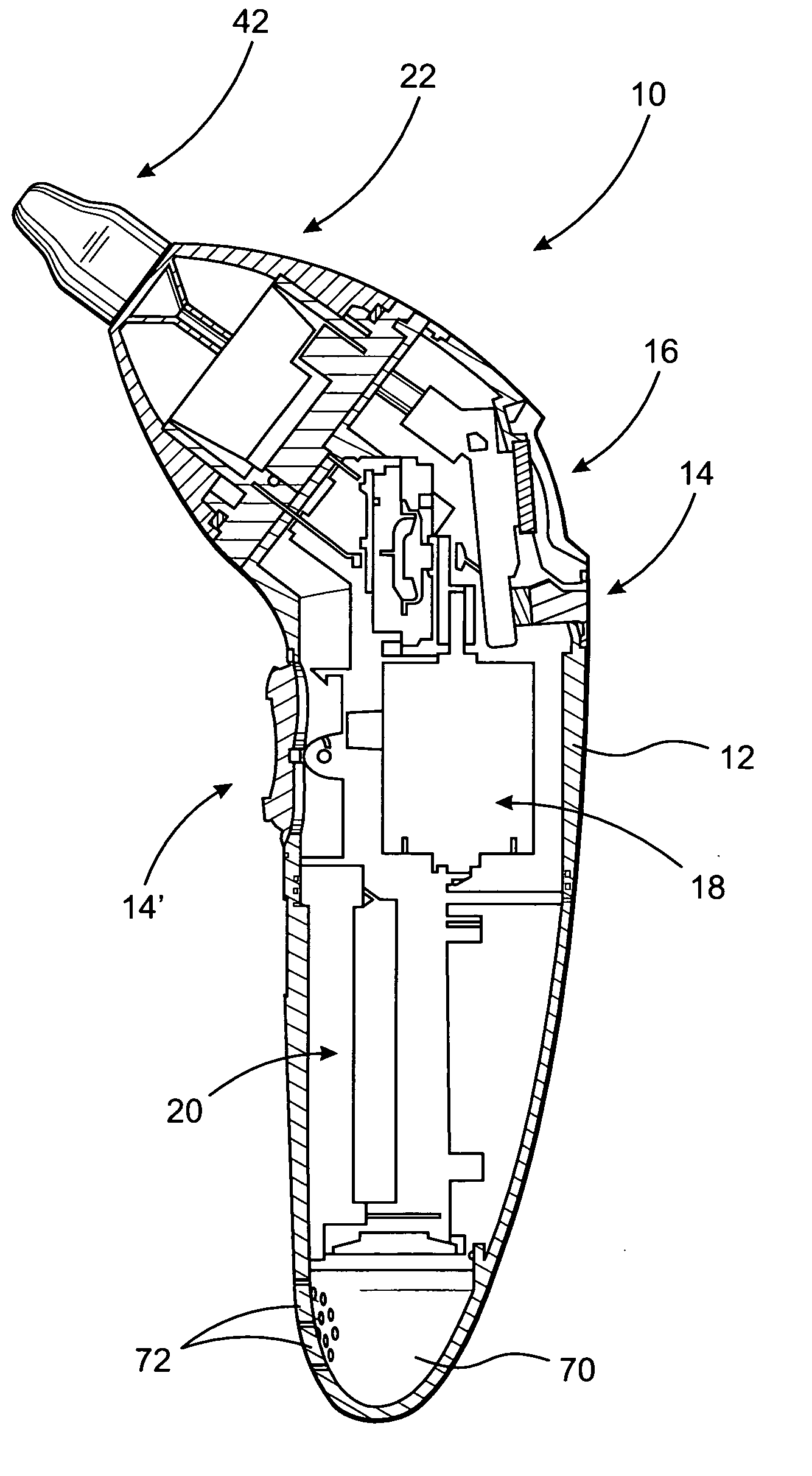
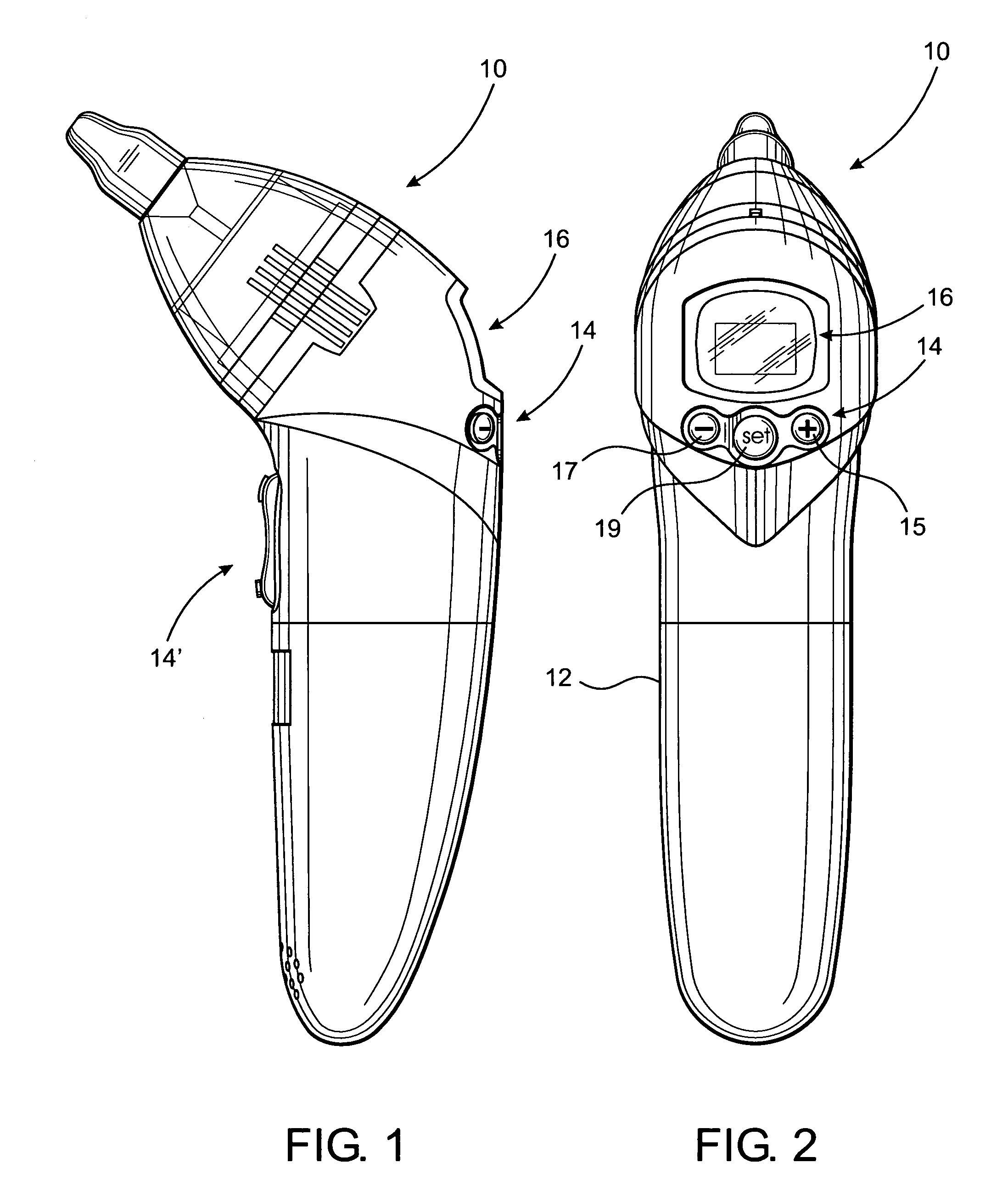
[0025]As shown in the accompanying Figures, the present invention is directed to an aspirator assembly generally indicated as 10 including an at least partially hollow interior casing 12, as represented in FIG. 3. The casing 12 is dimensioned and configured to be hand held and includes a plurality of operator buttons or like control members generally indicated as 14. The controls 14 facilitate activation and operation of the aspirator assembly 10 by a single hand of an operator. In conjunction therewith, a display assembly generally indicated as 16 is disposed in a readily observable location on the casing 12 and is cooperatively structured with appropriate control and operating circuitry (not shown) to allow visualization of the operational and performance characteristics of the aspirator assembly 10. Additional activation controls 14′ may also be disposed on the casing 12 and generally, but not exclusively, may be operatively connected to appropriate control circuitry to serve as ...


PUM


Abstract

An assembly structured aspirate nasal cavity of individuals including, but not limited to, children. A hand held and operative casing includes a negative pressure source preferably battery operated, and a cover assembly removably connected to the casing and structured to at least partially define a receiving chamber. An inlet assembly is formed in the casing and communicates with the negative pressure source at least partially by means of a path of fluid flow. A container is removably disposed within the receiving chamber in a predetermined, operative orientation sufficient to receive and collect a predetermined portion of the aspirated fluid, such as mucus removed from the nasal cavity. The path of fluid flow is disposed, dimensioned and structured to restrict passage of the heavier, predetermined portion of the aspirated fluid thereby facilitating its collection within the container, which is disposable along with the collected aspirated fluid after use.

Description

BACKGROUND OF THE INVENTION[0001]1. Field of the Invention[0002]This invention relates to a hand held aspirating assembly structured to aspirate fluid from the nasal cavity of individuals specifically including, but not limited to, infants and children. A source of negative pressure is battery powered and a receiving chamber is cooperatively structured to house a removable collection container. A predetermined portion of the aspirated fluid, such as mucus, is collected in the container and collectively disposed therewith after the aspiration procedure has been completed.[0003]2. Description of the Related Art[0004]The ordinary cold, as well as more serious respiratory infections, can result in the blockage of the nasal passage or cavity due to the accumulation of mucus therein. In the case of adult individuals the collected mucus can frequently or at least partially be removed by forced expulsion when the individual blows his or her nose. However, in the case of small children or in...

Claims


Application Information

Patent Timeline
Patent Type & Authority Applications(United States)
IPC IPC(8): A61M1/00
CPCA61M1/0003A61M2210/0618A61M2205/8206A61M2205/59A61M1/65
Inventor SEBBAN, ERIC
Owner VISIOMED GRP SA
Learn More