
Method for Operating a Radio Network and Subscriber Device for Said Type of Network

a subscriber device and radio network technology, applied in power management, high-level techniques, wireless commuication services, etc., can solve the problem of frequent limitation of the amount of energy available, and achieve the effect of reducing the amount of energy required for data transmission

Inactive Publication Date: 2009-02-19
SIEMENS AG
View PDF13 Cites 6 Cited by
  • Summary
  • Abstract
  • Description
  • Claims
  • Application Information

AI Technical Summary

Benefits of technology

The technical effect of this patent is finding ways to operate a radio network that reduces the amount of energy needed for sending data from one place to another, specifically among process instruments in an automation system. This will be achieved by developing a specialized device designed for this specific use case.

Problems solved by technology

The patent text describes a radio network for transmitting data between subscribers, which can also be referred to as sensor devices. The network has multiple radio cells, each containing a base station for wireless data transmission. To prevent interference between adjacent cells, different channels are used for wireless data transmission. When a mobile subscriber moves from one cell to an adjacent cell, a handover is required to switch to the new cell. To minimize delay time, the base stations simultaneously carry out test cycles, in which they transmit test signals into the radio cells to determine the best transmission channel for communication with the subscriber. This method is suitable for networks used for time-critical applications such as automation systems. The patent also mentions the increasing use of autonomous sensors in automation systems, which require a reliable and efficient communication network to transmit sensor values.

Method used


Image

  • Method for Operating a Radio Network and Subscriber Device for Said Type of Network
  • Method for Operating a Radio Network and Subscriber Device for Said Type of Network

Examples


Embodiment Construction

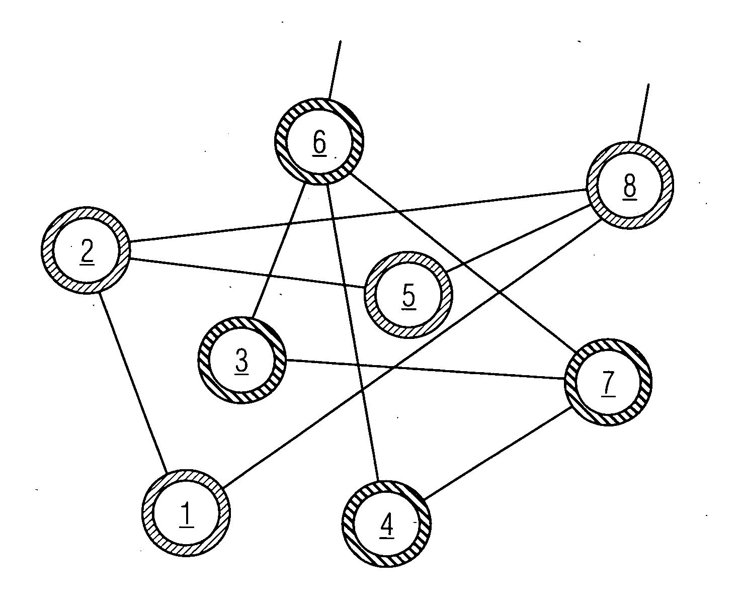
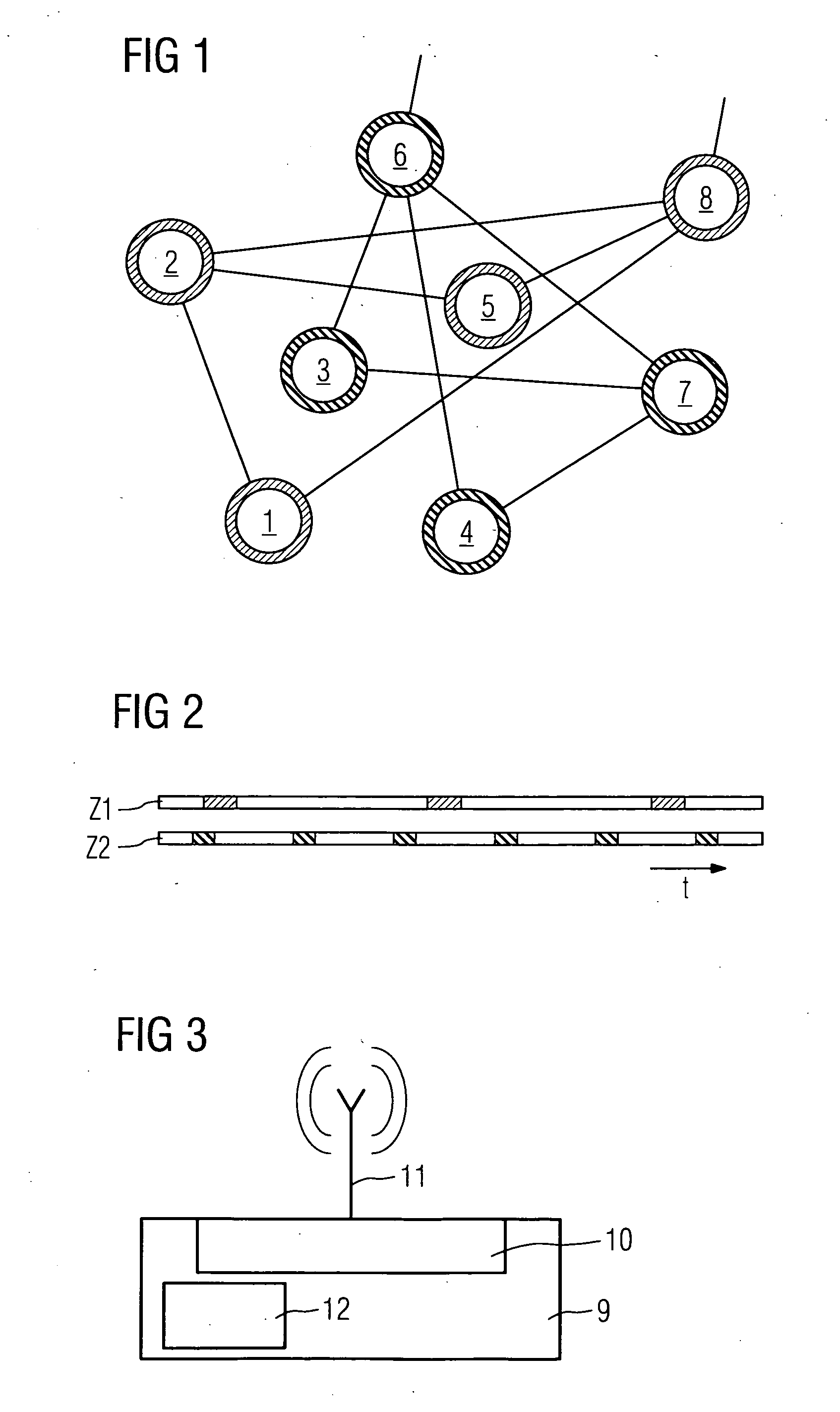
[0018]FIG. 1 shows an exemplary radio network with eight subscriber devices 1 . . . 8. In a start-up phase the subscriber devices 1 . . . 8 respectively send telegrams to notify the respective other subscriber devices of their requirements relating to data transmission frequency. During network optimization a configuration facility, which can be arranged centrally in the subscriber device 1 for example, determines from the subscriber devices 1 . . . 8 the communication partners, which suit one another best with regard to their requirements. In the meshed radio network shown in FIG. 1 this is done by means of a grouping, in which different subscriber devices are respectively connected together to form an independent meshed network. This can take place in such a manner that the subscribers start up temporally one after the other. Each subscriber broadcasts its requirements / functions, which are possible in the respective system, on all channels. It then receives a response from all the...


PUM


Abstract

There is described a method for operating a radio network for transferring data between several subscribers, in particular, between devices of process instrumentation in an automation system. At least one first subscriber communicates in a telegram the requests thereof relating to the frequency of the data transfer to other subscribers in a starting phase. During network optimization, a configuration device determines, in the radio network and according to the frequency of the requests of other subscribers, at least one communication partner to which a connection comprising the frequency of the data transfer, which is adapted to the other subscribers, is established. As the periods of data transfer are planned, it is possible to switch off the communication interface of the first subscriber in the pauses and also, to save energy.

Description


Claims


Application Information

Patent Timeline
Owner SIEMENS AG
Learn More