
Apparatus for enhanced information display in end user devices of a packet-based communication network

a packet-based communication network and display device technology, applied in the field of system and method of provisioning and maintaining network communications devices, can solve problems such as presenting technological, logistical and business challenges, service personnel working remotely, and encountering difficulties in trying to properly diagnose technical problems

Inactive Publication Date: 2009-02-19
VONAGE NETWORKS LLC
View PDF16 Cites 155 Cited by
  • Summary
  • Abstract
  • Description
  • Claims
  • Application Information

AI Technical Summary

Benefits of technology

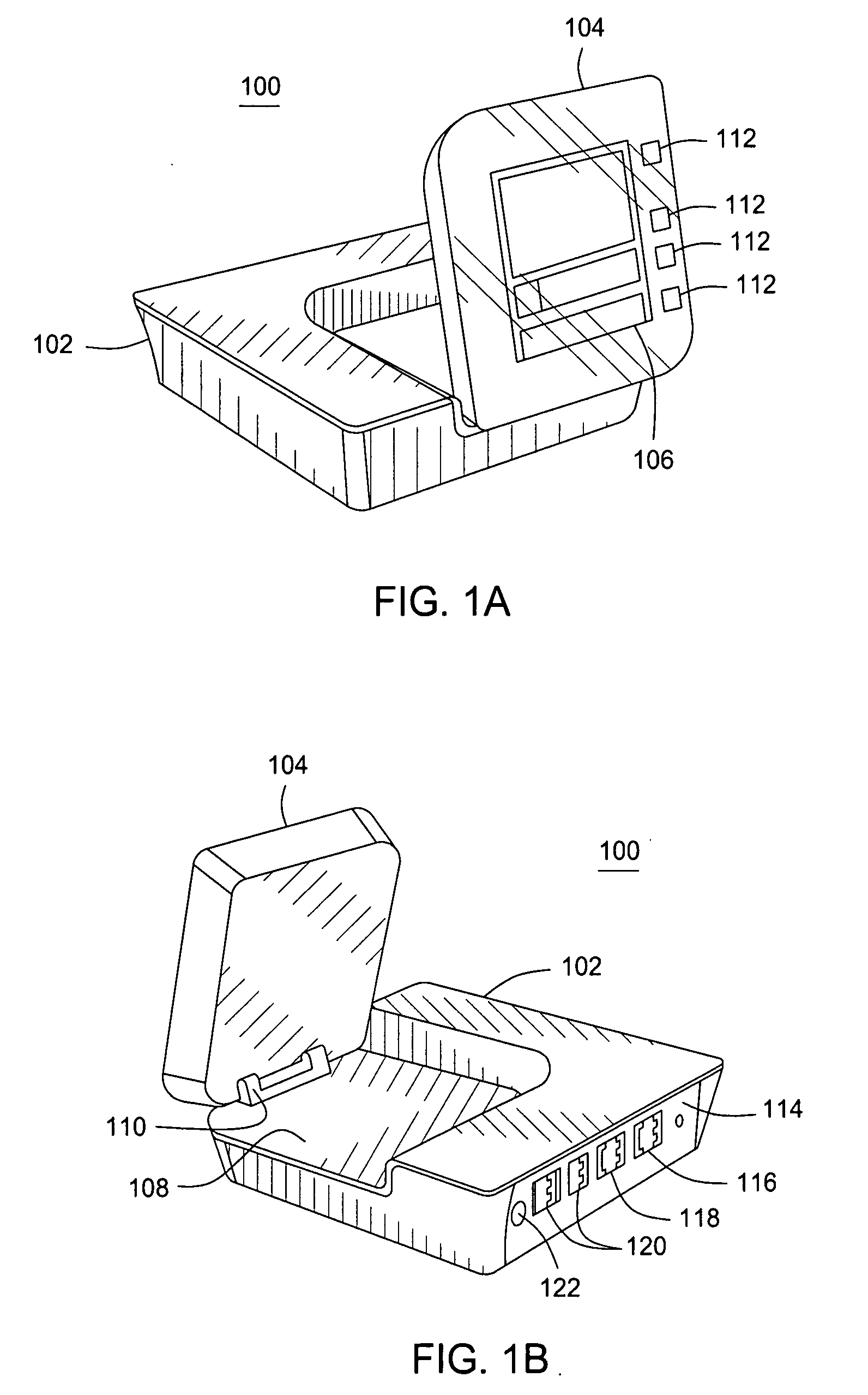
[0009]The apparatus for enhanced information conveyance includes a main body having at least one local area packet network connection means, at least one wide area packet network connection means and at least one non-packet network connection means for connection of a PSTN-based communication device and a display panel body adapted to display information regarding the status of the communication service in a non-binary manner. The display panel adaptation may be a display screen, one or more function buttons and a combination of such elements. The apparatus may have articulation means between the main body and display panel body for providing freedom of movement therebetween. The articulation means may be a hinge assembly, a set of telescoping members, a gimbal assembly and wireless means. In a preferred embodiment, the main body and the display panel body and integral with each other. The display panel body enhanced information conveyance means is responsive to communication service status messages from the packet-based communication service and those status messages are selected from messages included in the end user profile and messages provided by SIP messaging. Additionally, the display panel body enhanced information conveyance means is responsive to user-based requests to the packet-based communication service and such requests are selected from changing system features or apparatus settings associated with the end user device, reviewing call logs associated with the end user device, reviewing a status of user communication channels and inquiring about general system information.

Problems solved by technology

As service (and / or equipment) provider networks grow, the task of provisioning service and maintaining it for a large customer base presents technological, logistical, and business challenges.
Typically, when a communication failure occurs, (e.g., component failure, improper connection to the network or a power source, poor network traffic conditions and the like), extensive assistance must be provided to the end user by service personnel to diagnose the cause of the communication failure.
These service personnel working remotely (e.g., over the phone, via an online “chat” session and the like) encounter difficulties when trying to properly diagnose the technical issues based on the performance issues as described by an end user (including which lights may or may not be illuminated on the communication device).
In the frequent case that these symptoms or descriptions are incomplete or inaccurate, time and other resources are wasted in attempting to provide a solution to the problem.
Additionally, traditional communication devices are usually manufactured in ordinary rectangular shapes which are generally unappealing and lack a flair for design or visual impact.
As a result it is difficult to access the communication device to read the device status indicators and not generally possible to successfully display supplementary information to the user / subscriber that may be desirable.
In view of at least these two factors, there is a lack of information, understanding and aesthetics that greatly reduces the potential enjoyment of the overall broadband telephone experience.

Method used


Image

  • Apparatus for enhanced information display in end user devices of a packet-based communication network
  • Apparatus for enhanced information display in end user devices of a packet-based communication network
  • Apparatus for enhanced information display in end user devices of a packet-based communication network

Examples


first embodiment

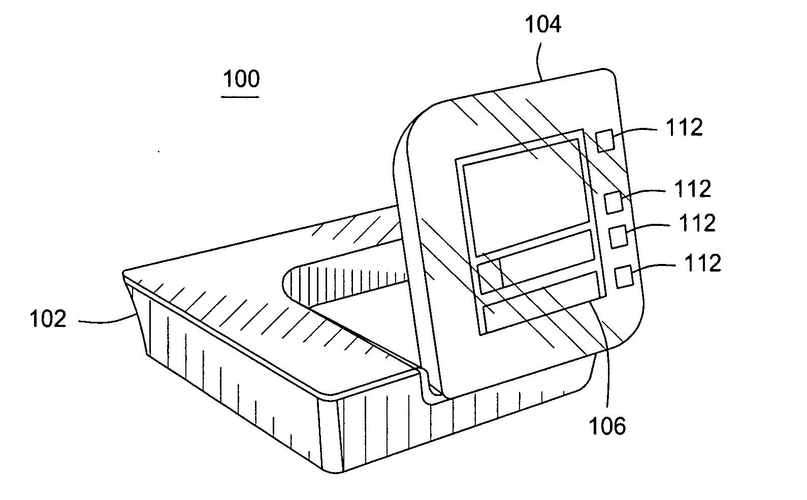
[0020]FIGS. 1A and 1B illustrate the invention as “single port” communication device 100. More specifically, FIG. 1A illustrates a front % perspective view and FIG. 1B illustrates a rear ¾ perspective view respectively of the communication device 100. Accordingly, the reader is directed to FIGS. 1A and 1B simultaneously in the following description. The phrase “single port” is defined as having one output port for connecting packet-based network devices.

[0021]In detail, the communication device 100 includes a main body 102 and a display panel body 104. The main body 102 further includes a recessed portion 108 into which the display panel body 104 can either be retracted into or extended away from. The retraction and extension movements are achievable by way of one or more articulation means 110. In one embodiment of the invention, the articulation means 110 is a hinge assembly where each of the main body 102 and display panel body 104 include a hinge member which are capable of rota...

second embodiment

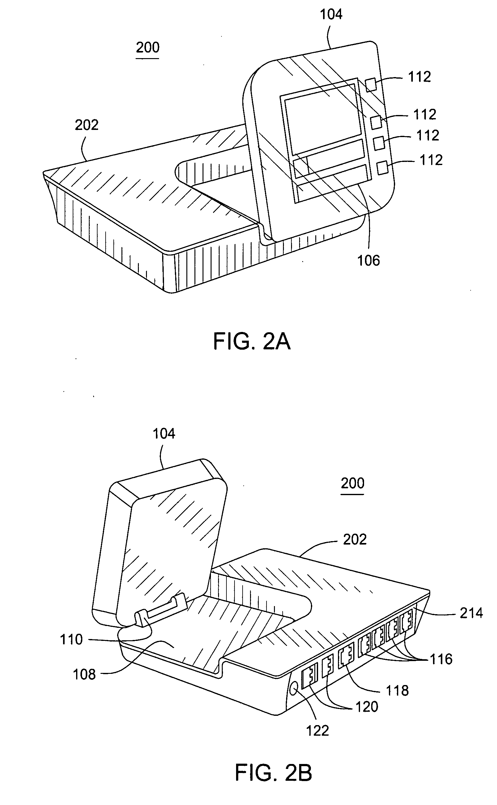
[0025]FIGS. 2A and 2B illustrate the invention as “multi-port” communication device 200. More specifically, FIG. 2A illustrates a front % perspective view and FIG. 2B illustrates a rear ¾ perspective view respectively of the communication device 200. Accordingly, the reader is directed to FIGS. 2A and 2B simultaneously in the following description. The phrase “multi-port” is defined as having more than one output port for connecting packet-based network devices.

[0026]In detail, the communication device 200 includes an elongate main body 202 and a display panel body 104. The elongate main body 202 is identical in form, function and features as the main body 102 of the first described embodiment 100 with the following differences. First, the elongate main body 202 is longer than main body 102 to accommodate additional hardware and LAN ports. Specifically, the elongate main body 202 includes an elongate rear panel 214 that has a plurality of first ports 116 for connections to local are...

third embodiment

[0028]FIG. 4 illustrates the invention as another “single port” communication device 400. More specifically, FIG. 4 illustrates a front 34 perspective view. For sake of clarity, a rear ¾ perspective view is not specifically shown, but is indicated as being identical in form and function to the rear % perspective view of the communication device 100 of FIG. 1B and the description of such embodiment provided earlier.

[0029]In detail, the communication device 400 includes a main body 402 having a display panel portion 404. The display panel portion 404 can either be contoured to be raised above or recessed below a top surface 408 of the main body 402. Alternately, the display panel portion 404 can be flush with the top surface 408.

[0030]Disposed within the display panel portion 404 is a plurality of enhanced information components to facilitate dissemination of enhanced status information about the communication device 400 and / or supplemental information to enhance user / subscriber enjoy...


PUM


Abstract

Method and apparatus for information conveyance in an end user device of a packet-based communication service where the end user device is connected to a PSTN-based communication device includes detecting a power up condition of the end user device connected to the PSTN-based communication device, detecting a packet-based network connection, retrieving an end user profile from the packet-based communication service attempting a communication registration operation and displaying one or more non-binary type messages at the end user device regarding the status of the communication service. The apparatus for enhanced information conveyance includes a main body having a local area packet network connection means, a wide area packet network connection means and a non-packet network connection means for connection of a PSTN-based communication device and a display panel body adapted to display information regarding the status of the communication service in a non-binary manner.

Description

CROSS-REFERENCE TO RELATED APPLICATIONS[0001]This application claims priority to U.S. Provisional Patent Application Ser. No. 60 / 934,650, filed Jun. 15, 2007, which is incorporated by reference herein in its entirety.FIELD OF THE INVENTION[0002]The present disclosure relates generally to systems and methods for provisioning and maintaining a network communications device. In particular, the present disclosure relates to devices and methods for providing enhanced information to Voice-over-IP (VoIP) subscribers.BACKGROUND[0003]In just a short time, VoIP has revolutionized the availability of affordable and advanced high-quality audio and visual communications. As VoIP has grown more popular, the size and complexity of service provider networks has increased immensely to handle the increased call volume and various service enhancements made possible by VoIP. As service (and / or equipment) provider networks grow, the task of provisioning service and maintaining it for a large customer ba...

Claims


Application Information

Patent Timeline
IPC IPC(8): H04L12/66
CPCH04M7/0069H04Q11/0471H04Q2213/13034H04Q2213/13389H04Q2213/13175H04Q2213/13202H04Q2213/13349H04Q2213/13172
Inventor SMIRES, DANIEL T.GRIKAS, MARYOTTUR, DEEPAK
Owner VONAGE NETWORKS LLC
Learn More