
Method for monitoring component life

a technology of component life and monitoring method, applied in the direction of instruments, combustion-air/fuel-air treatment, electric control, etc., can solve the problems of large memory and processor resources, high computational workload, and low accuracy of statistical analysis, so as to reduce the state of health of the filter and accurately predict the effect of the condition

Active Publication Date: 2019-04-09
FORD GLOBAL TECH LLC
View PDF30 Cites 1 Cited by
  • Summary
  • Abstract
  • Description
  • Claims
  • Application Information

AI Technical Summary

Benefits of technology

This approach allows for timely and accurate prediction of component lifespan, reducing the need for unnecessary maintenance and ensuring vehicle performance by providing clear, comprehensible maintenance alerts to operators.

Problems solved by technology

As another example, an air filter coupled to the engine intake may degrade based on the age of the filter, air quality, ambient weather conditions, etc.
However the inventors herein have identified various issues with such approaches.
As one example, the above approaches rely on statistical analyses that can be computationally intensive.
Consequently, they may require extensive memory and processor resources to assess the health of the air filter.
As another example, the availability of differential pressure measurements may be limited since not all engine systems include a differential pressure sensor around the air filter.
In some engine systems, no pressure sensors may be available around the air filter.
As still another example, the effects of different operating conditions on the pressure measurement may not be explicitly accounted, leading to unwanted bias in the assessments.
As yet another example, an operator may not be able to comprehend how much time is left before the air filter needs to be replaced when the filter health is indicated in terms of a percentage degradation.
The operator may replace the filter before the complete life of the filter has been used, resulting is the inefficient and uneconomical use of the filter.
Alternatively, the operator may delay replacement of the filter, compromising vehicle operation.
Further, the vehicle operator may not be able to timely modify their driving characteristics to avert filter degradation.

Method used


Image

  • Method for monitoring component life
  • Method for monitoring component life
  • Method for monitoring component life

Examples


Embodiment Construction

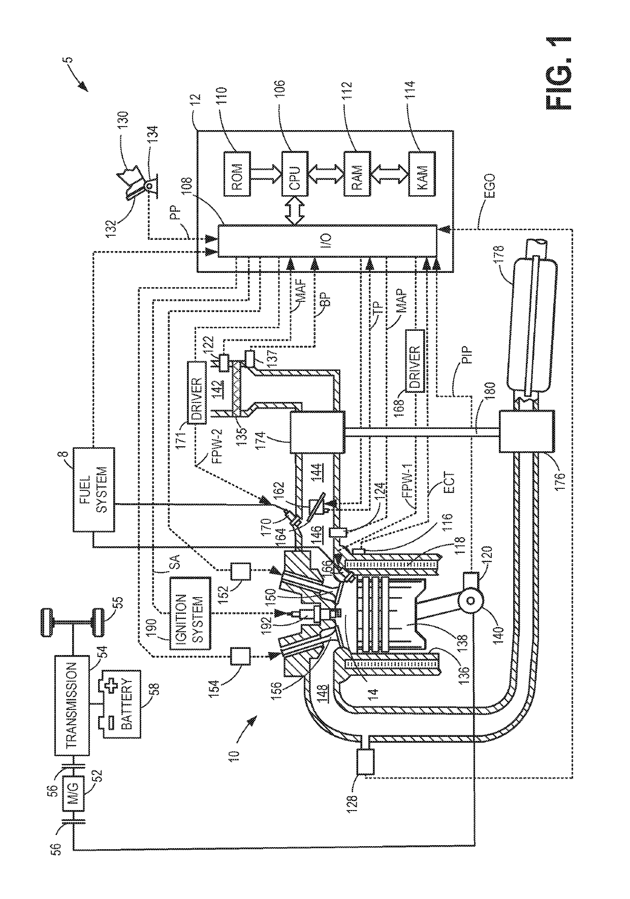
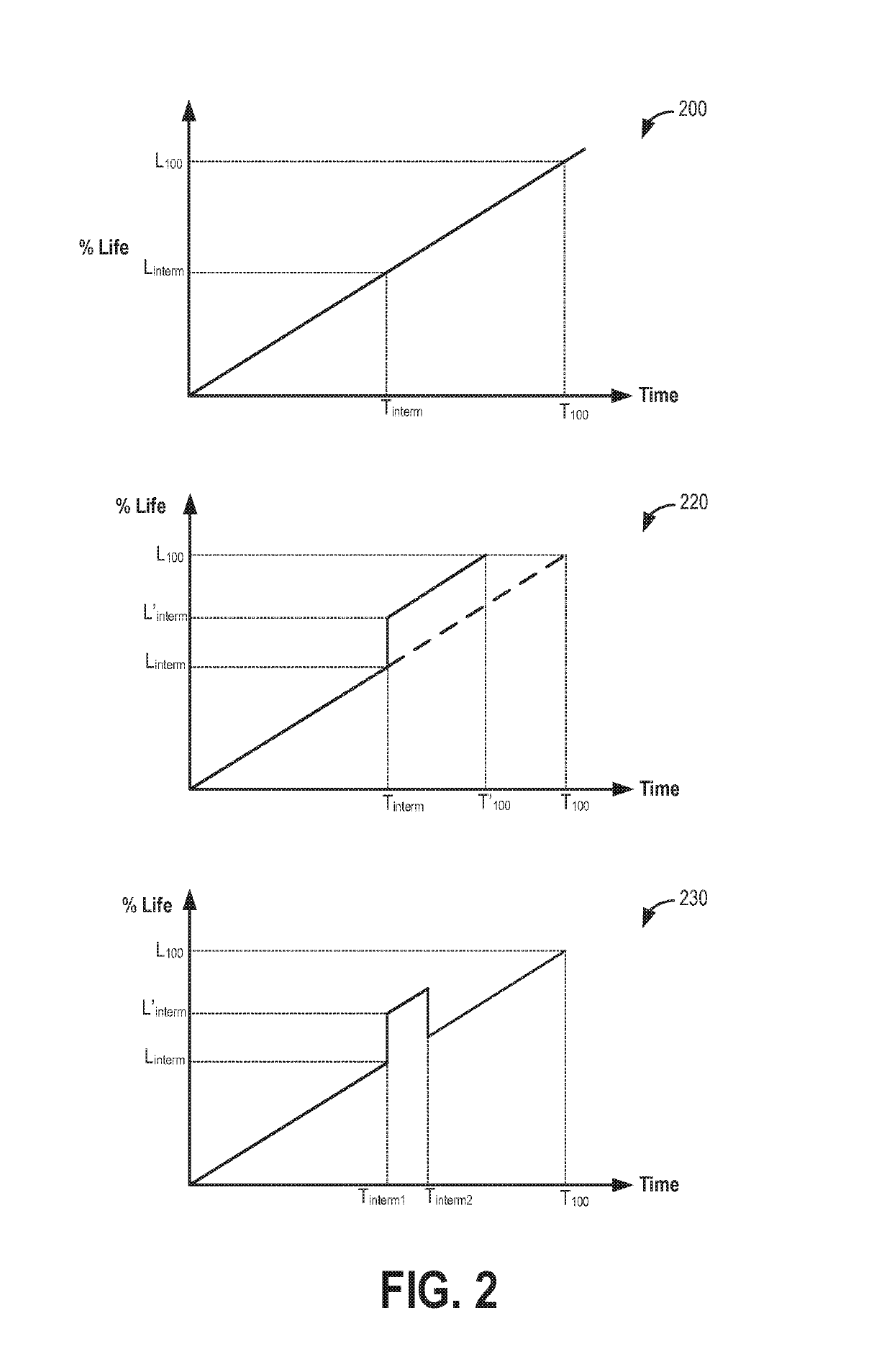
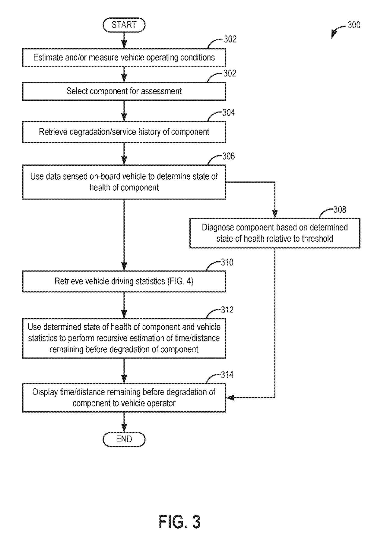
[0023]The following description relates to systems and methods for predicting the remaining life of a component of a hybrid vehicle system, such as the example vehicle system of FIG. 1. An engine controller may be configured perform a control routine, such as the example routines of FIGS. 3 and 4, to use statistical methods to predict the remaining life of a vehicle component. The controller may take into account the degradation history of the component as well as vehicle driving characteristics to map out percentage life profiles, such as the example profiles of FIG. 2. The controller may then use the percentage life profile to provide the vehicle operator of a remaining time or distance till the component needs to be serviced. Vehicle operations may then adjusted in accordance. A routine that predicts the remaining life of a vehicle battery (such as the routine of FIGS. 6-7) may rely on sensed and predicted changes in the resistance and capacitance of the battery, as shown with re...


PUM


Abstract

Methods and systems are provided for reliably prognosing a vehicle component, such as a vehicle battery or an intake air filter. A state of degradation of the component is predicted based on a metric that is derived from a sensed vehicle operating parameter, the parameter selected based on the component being diagnosed, as well as based on past driving history and future driving predictions. The predicted state of degradation is then converted into an estimate of time or distance remaining before the component needs to serviced, and displayed to the vehicle operator.

Description

FIELD[0001]The present application relates to methods performed in vehicles, such as hybrid vehicles, for estimating the remaining life of a vehicle component using statistical predictions.BACKGROUND AND SUMMARY[0002]Vehicles include various components which degrade at different rates and have to be serviced at different times. In addition, the degradation rate of each component may be affected by multiple parameters, some of which are overlapping with other components while others are non-overlapping. For example, in hybrid electric vehicles, a system battery may degrade based on the rate of battery usage, the age of the battery, temperature conditions, the nature of the battery, etc. As another example, an air filter coupled to the engine intake may degrade based on the age of the filter, air quality, ambient weather conditions, etc.[0003]Various approaches have been developed to assess the state of health of a vehicle component. One example approach for determining the state of h...

Claims


Application Information

Patent Timeline
Patent Type & Authority Patents(United States)
IPC IPC(8): F02M35/09F02M35/024F02M35/10F02M35/104G07C5/00
CPCF02M35/09F02M35/024G07C5/006F02M35/10386F02M35/104F02D9/02F02D41/0002F02M35/1038B60W40/00G01M15/04G08B25/10H04Q9/00
Inventor JAMMOUSSI, HASSENEMAKKI, IMAD HASSANLANDOLSI, FAKHREDDINEKUMAR, PANKAJ
Owner FORD GLOBAL TECH LLC
Learn More